XW60K 110918 V14.7 EMERSON092718 V14.7
XW60K
6/12
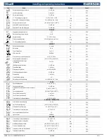
AFH
Differential for temperature alarm recovery:
(0.1 to 25.5°C; 1 to 45°F) intervention differential for recovery of temperature alarm.
ALd
Temperature alarm delay:
(0 to 255 min) time interval between the detection of an alarm condition and alarm signaling.
dAo
Exclusion of temperature alarm at start-up:
(0.0 to 24h00min, res. 10min) time interval between the detection of the temperature alarm condition after instrument power on and alarm signaling.
CONDENSER TEMPERATURE ALARM
AP2
Probe selection for temperature alarm of condenser:
(nP; P1; P2; P3; P4)
nP
= no probe;
P1
= thermostat probe;
P2
= evaporator probe;
P3
= discharge air probe;
P4
= Configurable probe.
AL2
Low temperature alarm of condenser:
(-55 to 150°C; -67 to 302°F) when this temperature is reached the
LA2
alarm is signaled, possibly after the Ad2 delay.
Au2
High temperature alarm of condenser:
(-55 to 150°C; -67 to 302°F) when this temperature is reached the
HA2
alarm is signaled, possibly after the
Ad2
delay.
AH2
Differential for temperature condenser alarm recovery:
0.1 to 25.5°C; 1 to 45°F.
Ad2
Condenser temperature alarm delay:
(0 to 255 min) time interval between the detection of the condenser alarm condition and alarm signaling.
dA2
Condenser temperature alarm exclusion at start up:
0.0 to 24h00min, res. 10min.
bLL
Solenoid off with low temperature alarm of condenser:
(n; Y)
n
= solenoid keeps on working;
Y
= solenoid is switched off till the alarm is present, in any case regulation restarts after
AC
time at minimum.
AC2
Solenoid off with high temperature alarm of condenser:
(n; Y)
n
= solenoid keeps on working;
Y
= solenoid is switched off till the alarm is present, in any case regulation restarts after
AC
time at minimum.
RELAY OA3 (22-23) CONFIGURATION
tbA
Alarm relay silencing (with oA3 =ALr):
(n; Y)
n
= silencing disabled: alarm relay stays on till alarm condition lasts.
Y
= silencing enabled: alarm relay is switched OFF by pressing a key during an alarm.
oA3
Third relay configuration (XW60K: terminals 22-23):
(dEF; FAn; ALr;
LiG
; AUS; onF; Cp2; db; dEF2; HES) dEF = defrost; FAn = do not select it; ALr = alarm;
LiG
= light
(Default)
; AUS = Auxiliary relay;
onF = always on with instrument on; db = neutral zone
(4.6)
; dEF2 = second defrost; HES = night curtain
AoP
(oA3=Alr)
Alarm relay polarity:
(CL; oP) it set if the alarm relay is open or closed when an alarm occurs.
CL
= terminals closed during an alarm;
oP
= terminals open during an alarm.
DIGITAL INPUT
i1P
First digital input polarity:
(oP; CL)
oP
= the digital input is activated by opening the contact;
CL
= the digital input is activated by closing the contact.
i1F
First digital input configuration:
(EAL; bAL; PAL; dor; dEF; ES; AUS; Htr; FAn; HdF; onF; Sbt)
EAL
= external alarm: “
EA
” message is displayed;
bAL
= serious alarm “
CA
” message is displayed;
PAL
=
pressure switch alarm, “
CA
” message is displayed;
dor = door switch function (use i2b)
;
dEF
= activation of a defrost cycle;
AUS
= auxiliary relay activation with
oA3=AUS
;
Htr
= type of inverting action (cooling
or heating);
FAn
= fan;
ES
= energy saving;
HdF
= Holiday defrost (enable only with RTC);
onF
= to switch the controller off
STANDBY
;
LHt = to activate the light.(Use Keyboard i2b=dor)
did
Digital input 1 alarm delay:
(0 to 255 min) delay between the detection of the external alarm condition and its signaling.
When
i1F= PAL
, it is the interval of time to calculate the number of pressure switch activation.
i2b
Second digital input on base (n,y)
n
= the second digital input is placed on the VX620 keypad. Use the (2) D.I. and (3) minus terminals.
y
= the second digital input is placed on the XW60K , use terminals 8-9.
+
D.I
-
i2P
Second digital input polarity:
(oP; CL)
oP
= the digital input is activated by opening the contact;
CL
= the digital input is activated by closing the contact.
i2F
Second digital input configuration:
(EAL; bAL; PAL;
dor
; dEF; ES; AUS; Htr; FAn; HdF; onF; Sbt) EAL
= external alarm:
“EA”
message is displayed; bAL = serious alarm
“CA”
message is displayed; PAL =
pressure switch alarm,
“CA”
message is displayed;
dor = door switch function
; dEF = activation of a defrost cycle; AUS = auxiliary relay activation with oA3=AUS; Htr = type of inverting action (cooling or
heating); FAn = fan; ES = energy saving; HdF = Holiday defrost (enable only with RTC); onF = to switch the controller off;
LHt = to activate the light (activated through
i2b=dor
)
d2d
Digital input 2 alarm delay:
(0 to 255 min) delay between the detection of the external alarm condition and its signalling.
When
i2F= PAL
, it is the interval of time to calculate the number of pressure switch activation.
nPS
Number of pressure switch activation:
(0 to 15) Number of activation, during the
did
or
d2d
interval, before signalling an alarm event (
i1F, i2F=PAL
).
If the
nPS
activation during
did
or
d2d
time is reached, switch off and on the instrument to restart normal regulation.
odC
Controller status when open door:
(no; FAn; CPr; F_C;)
no
= no effect
FAn
= FAN off;
CPr
= LLS Closed,
F_C
= Fan and LLS OFF.
rrd
Outputs restart after door open alarm:
(n; Y)
n
= outputs follow the
odC
parameter.
Y
= outputs restart with a door open alarm.
LES
Light off during Energy Saving status:
n; Y.
HES
Delta temperature during an Energy Saving cycle:
(-30.0 to 30.0°C; -54 to 54°F) it sets the increasing value of the set point
[SET+HES]
during the Energy Saving cycle.
Est
Energy Savings Timeout;
0 to 255 hours
9
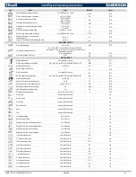
REAL TIME CLOCK PARAMETERS (OPTIONAL)
CURRENT TIME AND WEEKLY HOLIDAYS (ONLY FOR MODELS WITH RTC)
Hur
Current hour:
0 to 23h.
Min
Current minute:
0 to 59min.
dAY
Current day:
Sun to SAt.
dYM
Day of the month:
1 to 31.
Mon
Month:
1 to 12.
YAr
Year:
00 to 99.
Hd1
First weekly holiday:
(Sun to nu) set the first day of the week which follows the holiday times.
Hd2
Second weekly holiday:
(Sun to nu) set the second day of the week which follows the holiday times.
N.B.: Hd1, Hd2
can be set also as
“nu”
value (Not Used).
ENERGY SAVING TIMES (ONLY FOR MODELS WITH RTC)
ILE
Energy Saving cycle start during workdays:
(0 to 23h50min) during the Energy Saving cycle the set point is increased by the value in HES so that the operation set point is
SET+HES
.
dLE
Energy Saving cycle length during workdays:
(0 to 24h00min) sets the duration of the Energy Saving cycle on workdays.
ISE
Energy Saving cycle start on holidays:
0 to 23h50min.
dSE
Energy Saving cycle length on holidays:
0 to 24h00min.
TO SET DEFROST TIMES (ONLY FOR MODELS WITH RTC)
Ld1...Ld6
Workday defrost start:
(0 to 23h50min) these parameters set the beginning of the 6 programmable defrost cycles during workdays. Ex: when
Ld2=12.4
the second defrost starts at 12.40 during
workdays.
Sd1...Sd6
Weekend defrost start:
(0 to 23h50min) these parameters set the beginning of the 6 programmable defrost cycles on holidays. Ex: when
Sd2=3.4
the second defrost starts at 3.40 on holidays.
oA3=HES NIGHT CURTAINS or LIGHTS (ONLY FOR MODELS WITH RTC)
ILE
Energy Saving cycle start during workdays:
(0 to 23h50min) Start of the Energy Saving period the
oA3
relay is active.
dLE
Energy Saving cycle length during workdays:
(0 to 24h00min) sets the duration of the Energy Saving period the
oA3
relay is active on workdays.
ISE
Energy Saving cycle start on holidays:
0 to 23h50min.
dSE
Energy Saving cycle length on holidays:
0 to 24h00min.
Note: rtC parameters, t
o disable a defrost cycle set it to “nu” (not used).
OTHER
Adr
Serial address:
(1 to 247) identifies the instrument address when connected to a ModBUS compatible monitoring system.


