XW60K 110918 V14.7 EMERSON092718 V14.7
XW60K
7/12
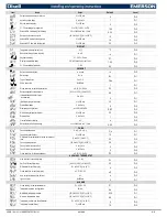
PbC
Type of probe:
(PtC; ntC) it allows to set the kind of probe used by the instrument:
-
PtC
= PTC probe;
ntC
= NTC probe.
onF
Energy Pig Key:
(nU; oFF; ES)
nU
= disabled;
oFF
= On/OFF;
ES
= Energy Saving Mode
dP1
Thermostat probe display.
dP2
Evaporator probe display.
dP3
Third probe display.
dP4
Fourth probe display
rSE
Real set point: it shows the set point used during the energy saving cycle or during the continuous cycle.
rEL
Software release for internal use.
Ptb
Parameter table code: readable only.
10
DIGITAL INPUT
The free voltage digital input is programmable in different configurations by the
i1F and i2F
parameters.
10.1
DOOR SWITCH INPUT (I2F = DOR) STANDARD
It signals the door status and the corresponding relay output status through the
odC
parameter:
no
= no change;
Fan
= Fan OFF;
CPr
= LLS Closed;
F_C
= Both LLS and fan OFF.
Since the door is opened, after the delay time set through parameter
did
, the door alarm is enabled, the display shows the message “
dA
” and
the regulation restarts is rtr = yES.
The alarm stops as soon as the external
digital input sees the door closed. With the door open, the high and low temperature alarms are disabled.
10.2
GENERIC ALARM (I1F = EAL) OPTIONAL
As soon as the digital input is activated the unit will wait for
did
time delay before signalling the “
EAL
” alarm message. The outputs status do
es
n’t change. The alarm stops just after the digital input is de
-activated.
10.3
SERIOUS ALARM MODE (I1F = BAL) OPTIONAL FOR LEAK DETECTOR
When the digital input is activated, the unit will wait for
did
delay before signalling the “
CA
” alarm message. The relay outputs are switched OFF. The alarm will stop as soon as the digital input is de
-activated.
10.4
PRESSURE SWITCH (I1F = PAL) OPTIONAL FOR CONDENSER ALARM
If during the interval time set by
did
parameter, the pressure switch has reached the number of activation of the
nPS
parameter, the “
CA
” pressure alarm message will be displayed. The
solenoid and the regulation are
stopped. When the digital input is ON the solenoid is always OFF.
If the nPS activation in the did time is reached, switch off and on the instrument to restart normal regulation.
10.5
AUXILIARY OUTPUT SWITCHING (I1F =AUS) OPTIONAL
With
oA3=AUS
and
i1F=AUX
it switches the fourth relay (22-23).
10.6
START DEFROST (I1F = DFR) OPTIONAL
It starts a defrost if there are the right conditions. After the defrost is finished, the normal regulation will restart only if the digital input is disabled otherwise the instrument will wait until the
MdF
safety time is expired.
10.7
KIND OF ACTION: HEATING OR COOLING (I1F = HTR) OPTIONAL
This function allows inverting the regulation of the controller: from cooling to heating and vice-versa.
10.8
ENERGY SAVING (I1F = ES) STANDARD I.E. GET A SIGNAL FROM A SMART METER
The Energy Saving function allows to change the set point value as the result of the
SET+HES
(parameter) sum. This function is enabled until the digital input is activated.
10.9
DIGITAL INPUTS POLARITY
The digital input polarity depends on the
i1P
parameter:
i1P=CL
: the input is activated by closing the contact.
i1P=OP
: the input is activated by opening the contact.
11
TTL/RS485 SERIAL LINE
The TTL connector allows, by means of the external module TTL/RS485
(XJ485CX)
, to connect the unit to a network line
ModBUS-RTU
compatible as the
dIXEL
monitoring system. The same TTL connector is used to
upload and download the parameter list of the
“
HOT-KEY
”
.
12
HOW TO: USE OF THE PROGRAMMING “HOT KEY”
12.1
PROGRAM A HOT-KEY FROM AN INSTRUMENT (UPLOAD)
1.
Program one controller with the front keypad.
2.
When the controller is ON
, insert the “
HOT-KEY
” and push
UP
button; the “
uPL
”
message appears followed a by a flashing “
End
” label.
3.
Push
SET
button and the “
End
” will stop flashing.
4.
Turn OFF
the instrument, remove the “
HOT-KEY
” and
then turn it ON again.
NOTE
: the
“
Err
” message appears in case of a failed programming operation. In this case push again button if you want to restart the upload
again or remove the “
HOT-KEY
” to abort the operation.
12.2
PROGRAM AN INSTRUMENT BY USING A HOT-KEY (DOWNLOAD)
1.
Turn OFF the instrument.
2.
Insert a
pre-programmed
“
HOT-KEY
”
into the 5-PIN receptacle
and then turn the Controller ON.
3.
The parameter list of the “
HOT-KEY
” will be automatically downloaded into the Controller memory. The “
doL
” message will blink followed a by a flashing “
End
”
label.
4.
After 10 seconds the instrument will restart working with the new parameters.
5.
Remove the “
HOT-KEY
”.
NOTE:
the message “
Err
” is displayed for failed programming. In this case turn the unit off and then on if you want to restart the download again or remove the “
HOT-KEY
” to abort the operation.


