XW60K 110918 V14.7 EMERSON092718 V14.7
XW60K
8/12
13
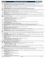
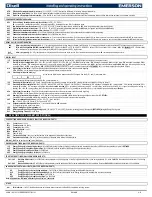
ALARM SIGNALS
Message Cause
Outputs
P1
Thermostat probe failure
Alarm signal ON; Solenoid output according to parameters
Con
and
CoF
.
P2
Evaporator probe failure
Alarm signal ON; Other outputs unchanged
P3
Probe 3 probe failure
Alarm signal ON; Other outputs unchanged
P4
Probe 4 probe failure
Alarm signal ON; Other outputs unchanged
HA
Maximum temperature alarm
Alarm signal ON; Other outputs unchanged
LA
Minimum temperature alarm
Alarm signal ON; Other outputs unchanged
HA2
Condenser high temperature
It depends on the
AC2
parameter
LA2
Condenser low temperature
It depends on the
bLL
parameter
dA
Door open
Solenoid and fans restart
EA
External alarm
Output unchanged.
CA
Serious external alarm (i1F=bAL) All outputs OFF.
CA
Pressure switch alarm (i1F=PAL) All outputs OFF
EE
Data or memory failure
Alarm signal ON; Other outputs unchanged
The alarm message is displayed until the alarm condition is recovered.
All the alarm messages are shown alternati
ng with the room temperature except for the “P1” which is flashing.
To reset the “EE” alarm and restart the normal functioning press any key, the “
rSt
” message is displayed for about 3
sec.
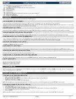
13.1
SILENCING BUZZER
Once the alarm signal is detected the buzzer can be silenced by pressing any key. Buzzer is mounted in the keyboard.
13.2
“EE” ALARM
The
dIXEL
instruments are provided with an internal check for the data integrity. The
“EE”
alarm flashes when a failure in the memory data occurs. In such cases the alarm output is enabled.
13.3
ALARM RECOVERY
Probe alarms: “
P1
” (probe1 faulty), “
P2
”, “
P3
” and “
P4
”; they automatically stop 10
sec after the probe restarts normal operation. Check connections before replacing the probe.
Temperature alarms “
HA
”, “
LA
” “
HA2
” and “
LA2
” auto
matically stop as soon as the temperature returns to normal values.
Alarms
“EA”
and
“CA”
(with
i1F=bAL
)
recover as soon as the digital input is disabled.
Alarm “
CA”
(with
i1F=PAL
) recovers only by
switching off and on
the instrument.
14
INSTALLATION AND MOUNTING
T620
keyboard shall be mounted on vertical panel, in a 150x31 mm hole, and fixed using two screws
3 x 2mm. To obtain an IP65 protection grade use the front panel rubber gasket (mod. RG-L).
VX620
keyboard shall be mounted on vertical panel, in standard low voltage J-Box, and fixed using two screws
3 x 2mm. To obtain an IP65 protection grade use the front panel rubber gasket included (mod. RGW-V).
CX620
keyboard shall be mounted on vertical panel, in a 29x71 mm hole, and fixed using the special bracket supplied.
The controller
XW60K
can be mounted in a din rail or wall mounted. It must be connected to the keyboard by means of a two-wire cable (
1mm). The ambient temperature range should be -10 to 60°C/14
–
140F (Avoid
places subject to strong vibrations, corrosive gases, excessive dirt or humidity. The same recommendations apply to probes. An enclosure is recommended for certain environments.
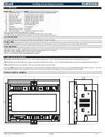
14.1
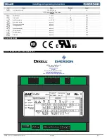
XW60K
–
8 DIN CASE
–
DIMENSIONS


