XW60K 110918 V14.7 EMERSON092718 V14.7
XW60K
9/12
15
ELECTRICAL CONNECTIONS
XW60K
is provided with screw terminal blocks to connect cables with a cross section up to 2.5 mm
2
for the RS485 (optional) and the keyboard. To connect the other inputs, power supply and relays,
XW60K
is provided with
Faston connections (6.3mm). Heat-resistant cables should
be used. Before connecting cables make sure the power supply complies with the instrument’s requirements. Separate the probe
cables from the power supply
cables, and from the outputs and the power connections. Do not exceed the maximum current allowed on each relay, in case of heavier loads use a suitable external relay.
NOTE:
the maximum current allowed for all the loads is 16A.
15.1
PROBE CONNECTIONS
The probes shall be mounted with the bulb angled upwards to prevent damage due to casual liquid infiltration. It is recommended to place the return air probe to correctly measure the average room temperature. Place the
defrost termination probe among the evaporator fins in the coldest place, where most ice is formed, far from heaters or from the warmest place during defrost, to prevent premature defrost termination. Place the Discharge
Air Probe on the discharge side of the evaporator.
16
Technical data
KeyPads
Housing:
self extinguishing ABS
Case: T620 and T620T:
face 38x185 mm; depth 23mm
VX620:
face 72x56 mm; depth 23mm;
CX620:
face 75x36 mm; depth 23mm
Mounting:
T620T
panel mounting in a 150x31 mm panel cut-out with the 2 metal brackets supplied.
VX620:
panel mounting in a standard J-Box, can be low voltage
CX620:
panel mounting in a 71x29mm panel cut-out
Frontal protection:
IP65 with frontal gasket
Connections:
Screw terminal block
2.5 mm
2
Power supply:
from
XW60K
power module
Display
: 3 digits, red LED, 14.2 mm high
Alarm Output
: buzzer.
Power module XW60K
Case: 8 DN:
140X176X148
Connections:
Screw terminal block
2.5 mm
2
heat-resistant wiring and 6.3mm Faston
Power supply:
230Vac or. 110Vac
10% or 24Vac
Power absorption:
6VA max
Inputs
: 4 NTC or PTC probes
Digital inputs
: 2 free voltage
Relay outputs:
Total current on loads MAX. 16A
Liquid Line Solonoid:
relay SPST 8 A, 250Vac
Fan:
relay SPST 16 A, 250Vac
Defrost:
relay SPST 16A, 250Vac
Light (oA3):
relay SPST 16A, 250Vac
Serial output:
TTL standard
Communication protocol:
Modbus - RTU
Data storing
: on the non-volatile memory (EEPROM)
Kind of action:
1B
Pollution degree:
normal
Software class:
A
Operating temperature:
-10 to 60°C (14 to 140°F)
Storage temperature:
-25 to 60°C (-13 to 140°F)
Relative humidity:
20 to 85% (no condensing)
Measuring and regulation range:
NTC probe:
-40 to 110°C (-58 to 230°F)
PTC probe:
-50 to 150°C (-58 to 302°F)
Resolution:
0.1°C or 1°C or 1°F (selectable)
Accuracy (ambient temp. 25°C):
±0.5°C ±1 digit
17
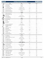
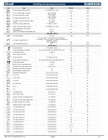
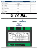
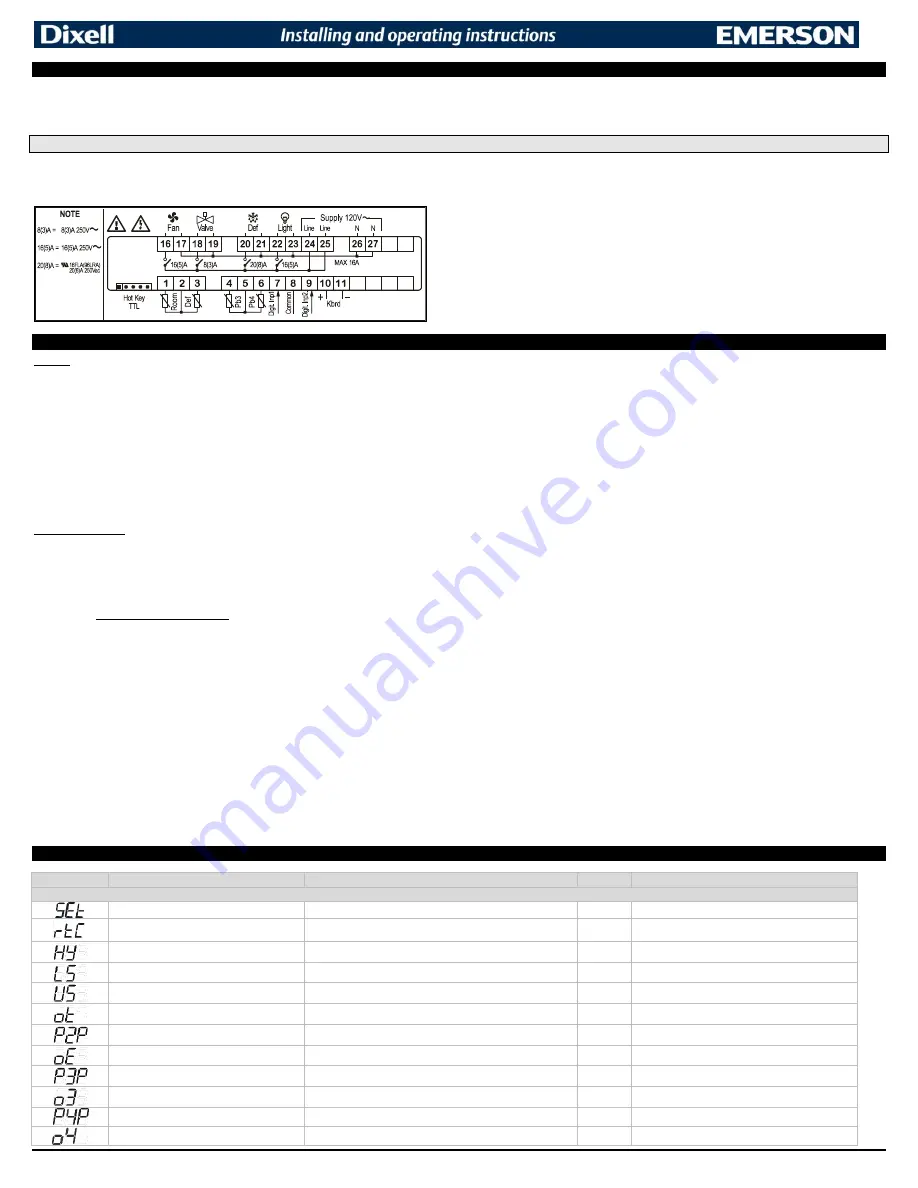
Default setting values
Label
Name
Range
Default
Level
REGULATION
Set point
LS; US
0
- - -
*
Real time clock menu
(OPTIONAL)
-
-
Pr1
Differential
[0.1 to 25.5°C] [1 to 45°F]
4
Pr1
Minimum set point
[-55.0°C to SET] [-67°F to SET]
-58
Pr2
Maximum set point
[SET to 150°C] [SET to 302°F]
230
Pr2
Thermostat probe calibration
[-12 to 12°C] [-21 to 21°F]
0
Pr1
Evaporator probe presence
n=not present; Y=pres.
yes
Pr1
Evaporator probe calibration
[-12 to 12°C] [-21 to 21°F]
0
Pr2
Discharge Air Probe presence
n=not present; Y=pres.
no
Pr2
Third probe calibration
[-12 to 12°C] [-21 to 21°F]
0
Pr2
Fourth probe presence (opt. cond. probe)
n=not present; Y=pres.
no
Pr2
Fourth probe calibration
[-12 to 12°C] [-21 to 21°F]
0
Pr2


