


1592028000 XWEB300D_500_500D opr GB r2.2.0 2013.08.01.docx XWEB500/300 11/114
2
2
I
I
N
N
S
S
T
T
A
A
L
L
L
L
A
A
T
T
I
I
O
O
N
N
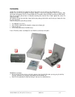
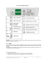
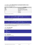
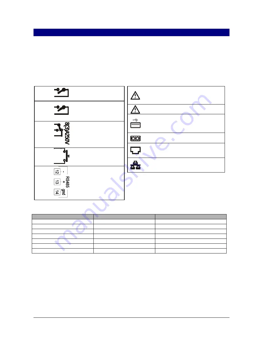
2.1 HARDWARE
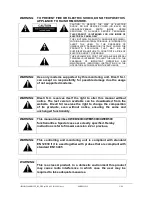
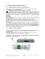
ATTENTION: to protect both yourself and the server from electrical hazards the XWEB should remain turned
off until you are finished connecting all electrical devices to the unit.
To avoid accidental start of the unit, remember to plug in electrical cable only when you have
finished setting up all other connection.
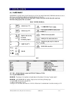
(ONLY FOR DIN MODELS)
3
: alarm relay 1 (**)
4
5
: alarm relay 2 (**)
6
7
: System alarm relay
:7-8 Alarm
:7-9 Alarm present
8
9
15
: digital input (**)
16
12 (
-
)
: RS 485
13 (
+
)
14 (
)
: 1-2 XWEB500 Power supply
: 10-11 External GSM modem power
supply (*)
: USB external peripherals
: COM port for external modem
: Telephone jack (only for internal
modem)
: RJ45 LAN connector
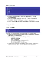
LED
Led
Color
Description
Alarm
Red
RS485 Alarm
Rec
Orange
Data recording
Power
Green
System turned on
Status
Green
Messages are being sent
System
Red
System alarm
Alarm2
Red
Alarm Relay 2 status
Alarm1
Red
Alarm Relay 1 status
(*)= 12Vcc - 250mA. Modem supported TC35-KIT (Siemens TC55i)
(**)= only for XWEB500DIN
WARNING:
The status of led system is directly linked to the status of the relay
“System alarm”.
WARNING:
with XWEB300D the 'system relay’ acts as AUX taking following logic:
• at rest (XWEB off) closed contacts 7:09
• in case of alarm closes on 7-8
• turning on for a few seconds closes on 7-8. then if there are no alarms back to rest and closing on 7-9.
Summary of Contents for Dixell XWEB300
Page 1: ...OPERATION MANUAL v 2 2 0 ...
Page 2: ...1592028000 XWEB300D_500_500D opr GB r2 2 0 2013 08 01 docx XWEB500 300 2 114 ...
Page 80: ...1592028000 XWEB300D_500_500D opr GB r2 2 0 2013 08 01 docx XWEB500 300 80 114 ...
Page 96: ...1592028000 XWEB300D_500_500D opr GB r2 2 0 2013 08 01 docx XWEB500 300 96 114 ...


