


1592028000 XWEB300D_500_500D opr GB r2.2.0 2013.08.01.docx XWEB500/300 12/114
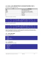
(ONLY FOR COOLMATE MODELS)
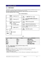
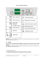
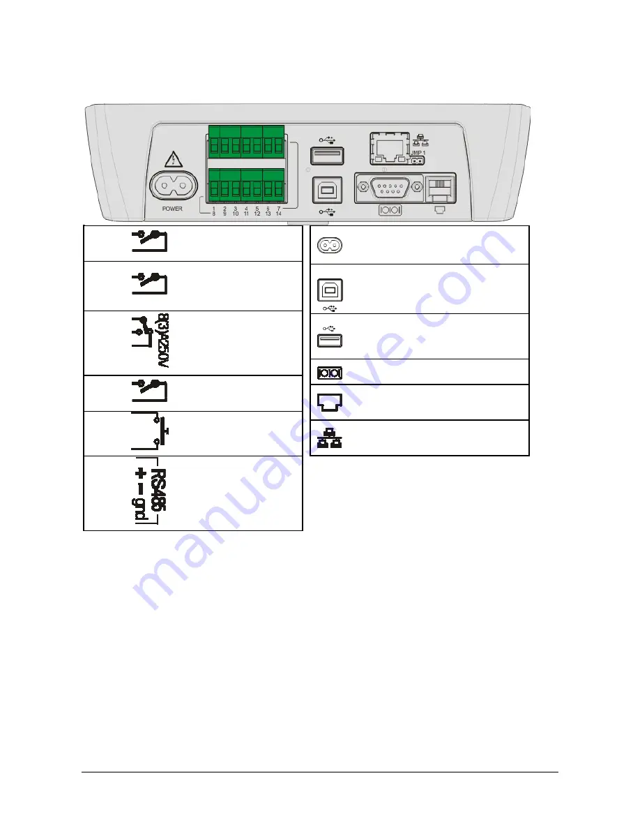
1
: Alarm 1 output relay
2
3
: Alarm 2 output relay
4
5
: System Alarm
:5-6 No Alarm
:5-7 At least one alarm
6
7
8
: modem reset relay
9
10
: digital input
11
12 (+)
: RS 485 socket
13 (
-
)
14 (
)
: Power supply connector
: USB socket for PC connection
: USB socket for devices connection
: External modem socket
: Internal modem line connector
: RJ45 Ethernet connector
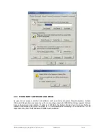
WARNING:
the relay 'reset modem' is excited to reset, under conditions of disuse every two minutes and
before each use (to fax, to dial-up, etc..).
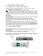
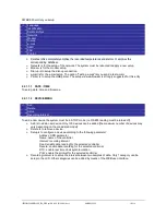
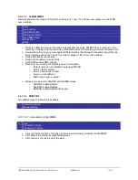
2.1.1 RS485
To be connected to the serial line all the Dixell Modbus instruments must be provided with direct RS485
terminals or the “TTL”-RS485 interface (XJRS485 or XJ485). Check the instrument manuals for more
information.
The RS485 line is mainly based on two polarised terminals. Please beware to respect the right sequence for
all the devices connected to the serial line.
Follow these important advises:
The RS485 serial line must reach all the instruments where they are installed.
Beware to the wire polarities when screwing them into the instrument terminals.
Summary of Contents for Dixell XWEB300
Page 1: ...OPERATION MANUAL v 2 2 0 ...
Page 2: ...1592028000 XWEB300D_500_500D opr GB r2 2 0 2013 08 01 docx XWEB500 300 2 114 ...
Page 80: ...1592028000 XWEB300D_500_500D opr GB r2 2 0 2013 08 01 docx XWEB500 300 80 114 ...
Page 96: ...1592028000 XWEB300D_500_500D opr GB r2 2 0 2013 08 01 docx XWEB500 300 96 114 ...


