EC2-712_65108_EN_R03.doc
Replacement for Rev.:02
1 / 4
16.09.2009
EC2-712 Condenser Controller
Operating Instructions
GB
Note: This document contains short form instructions for experienced users.
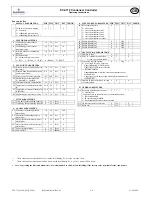
Use last column in List of Parameters to document your individual settings.
More detailed information can be found in the User Manual.
The
EC2-712
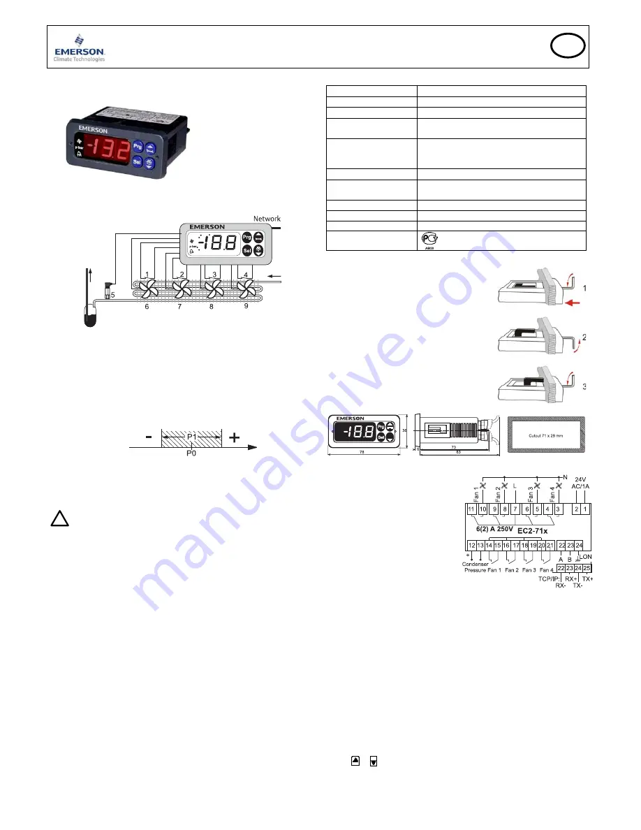
has been designed to control condensers with up to four fans. The
purpose of the controller is to keep condensing pressure to a minimum by
switching fans on or off.
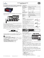
The PT5 pressure transmitter (5) senses condensing pressure and feeds the signal
into a condensing pressure dead band control loop. Condensing pressure is
modulated by turning fan motors on and off.
No change occurs as long as the condensing pressure remains within the dead band
(P1) around the condensing pressure setpoint (P0). The controller will add/remove
fan capacity when the condensing pressure goes beyond the limits of the
condensing pressure dead band. For stable condenser operation, adjustable time
delays for fan motor on and off are available. To avoid premature wear of
individual fan motors, run time equalization is built into the controller.
remove capacity
dead band
add capacity
Condensing
Pressure
A fast recovery procedure can be used to immediately switch off all fans when the
condensing pressure falls below a set limit. Similarly an emergency routine can be
activated automatically if the condensing pressure exceeds a definable limit.
!
Safety instructions:
•
Read installation instructions thoroughly. Failure to comply can result in
device failure, system damage or personal injury.
•
The product is intended for use by persons having the appropriate
knowledge and skills.
•
Ensure electrical ratings per technical data are not exceeded.
•
Disconnect all voltages from system before installation.
•
Keep temperatures within nominal limits.
•
Comply with local electrical regulations when wiring
Technical data:
Power supply
24VAC ±10%; 50/60 Hz; Class II
Power consumption
4VA max.
Communication TCP/IP
Ethernet
10MBit/s
Terminals
Removable screw terminals
wire size 0.14 … 1.5 mm
2
Temperature
storage
operating
-20 … +65°C
0 … +60°C
Pressure sensor input
24VDC, 4 … 20mA
Fan output relays
Inductive (AC15) 250V / 2A
Resistive (AC1) 250V / 6A; 12A total return current
Digital inputs
Volt free contacts 5V/0,1mA
Humidity
0 … 80% rh. non condensing
Protection class
IP65 (front protection with gasket)
Marking
Mounting
The EC2-712 can be mounted in panels with a 71 x
29 mm cutout. See dimensional drawing below for
space requirements including rear connectors.
Push controller into panel cutout.(1)
Make sure that mounting clamps are flush with
outside of controller housing
Insert allen key into front panel holes and turn
clockwise. Mounting clamp will turn and gradually
move towards panel (2)
Turn allen key until mounting clamp barely touches
panel. Then move other mounting clamp to the same
position (3)
Tighten both sides very carefully until controller is
secured. Do not over tighten as mounting clamps
will break easily.
Electrical Installation
Refer to the electrical wiring diagram
(right) for electrical connections. A copy
of this diagram is labelled on the
controller.
Use connection wires/cables suitable for
90°C operation (EN 60730-1).
EC2 analog inputs are for dedicated
sensors only and should not be connected
to any other devices. Volt free digital
inputs should only be connected to serial
control loops or relays with gold
contacts. They should not be connected
to any other devices
Important:
Keep controller and sensor wiring well separated from mains wiring.
Minimum recommended distance 30mm.
Warning:
Use a class II category transformer for 24VAC power supply
(EN 60742). Do not ground the 24VAC lines. We recommend to use one
transformer per EC2 controller and to use separate transformers for 3
rd
party
controllers, to avoid possible interference or grounding problems in the power
supply. Connecting any EC2 inputs to mains voltage will permanently damage the
EC2.
Set-up and Parameter Modification Using the Keypad
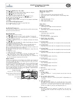
For convenience, an infrared receiver for the optional
IR remote control unit
is
build-in, enabling quick and easy modification of the system parameters when a
computer interface is not available.
Alternatively, the parameters can be accessed via the 4-button keypad. The
configuration parameters are protected by a numerical password. The default
password is “12”. To select the parameter configuration:
•
Press the
PRG
button for more than 5 seconds
A flashing 0 is displayed
•
Press or until 12 is displayed; (password)
•
Press
SEL
to confirm password
•
The first modifiable parameter code is displayed (/1).
•
To modify parameters see Parameters modification below.

