EC2-712_65108_EN_R03.doc
Replacement for Rev.:02
3 / 4
16.09.2009
EC2-712 Condenser Controller
Operating Instructions
GB
Fan controller
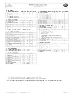
/ DISPLAY PARAMETERS Min Max Unit
Def
Individ.
/1 Value to be shown on display
0
2
-
0
0 = Fan states
1 = condensing pressure (bar)
2 = condensing temperature (°C)
r
SENSOR PARAMETERS
r0 Condensing pressure sensor
minimum value
-1.0 50 bar 0.0
r1 Condensing pressure sensor
maximum value
-1.0 50 bar 30
r2 Pressure offset for condensing
pressure
-1.0 1.0 bar 0.0
r3 Refrigerant
type
0
5
-
4
0 = no temperature conversion;
1 = R22; 2 = R134a; 3 = R507; 4 = R404A; 5 = R407C
P SET-POINT PARAMETERS
P0 Pressure set-point (condensing) for
fan circuit
-1.0 50 bar 14.0
P1 Pressure band (dead band for dead
band control mode)
0.0 50 bar 4.0
P3 Fast recovery from low pressure
-9.9 50.0
bar
9
P4 Enable set-point compensation
0 = disabled; 1 = enabled
0 1 - 0
P5 Maximum pressure compensation
-3.0 3.0
bar
-3.0
P6 Temperature at minimal shift value
(0)
-50.0
50 °C 30
P7 Temperature at maximal shift value
(Shift Max)
-50.0
50 °C 15.0
P8 High discharge pressure recovery.
-9.9
50
bar
20
t TIME PARAMETERS
t1
(1)
Time delay before adding capacity 0
99
10sec
3
t2
(1)
Time delay before removing capacity
0
99
10sec
3
A ALARM PARAMETERS
A2 Minimum condensing pressure
alarm limit
-1.0 50 bar 10.0
A3 Maximum condensing pressure
alarm limit
-1.0 50 bar 27
A4
(1)
Delay time for minimum pressure
alarm limit
0 99 10sec 0
A5
(1)
Delay time for maximum pressure
alarm limit
0 99 10sec 0
A8
(1)
Fan serial alarm delay
0
99
10sec
0
A9
(2)
Fan run limit
0
99 10000hr
0
u STEP ENABLE PARAMETERS Min Max Unit
Def
Individ.
u0 Reset operating time
0 = do nothing
1 = reset operating time fan 1
2 = reset operating time fan 2
3 = reset operating time fan 3
4 = reset operating time fan 4
5 = reset operating time all fans
0 5 - 0
u1 Enable/disable fan 1
0
1
flag
1
u2 Enable/disable fan 2
0
1
flag
1
u3 Enable/disable fan 3
0
1
flag
1
u4 Enable/disable fan 4
0
1
flag
1
C
APPLICATION PARAMETERS
C1 Number of fans
1
4
-
4
C4 Fan 1 (0 = standard control loop
1 = fan 1 act as base load)
0 1 - 0
C5 Fan switch logic (Rotation)
0
1
flag
1
0 = FILO logic (First In, Last Out)
Capacity demand: Adds first fan.
Capacity excess: Removes last fan.
1 = Rotation enabled
Capacity demand: Adds fan with lowest runtime out of
available fans.
Capacity excess: Removes fan with highest runtime out of
available fans.
C6 Number of fans to switch on in case
of sensor failure
0 4 - 0
H
OTHER PARAMETERS
H2 Keyboard and IR remote control
0
3
-
3
0 = all disabled
(Caution, access to controller only via network possible)
1 = Keyboard enabled
2 = IR remote control enabled
3 = Keyboard and IR remote control enabled
H3 IR remote control access code
0
199
-
0
H5 Password
0 199
-
12
(1)
These values have a resolution of 10 sec,
on the local display. Ex. A value 1 means 10 sec.
(2)
These values have a resolution of 10.000 hours,
on the local display. Ex. A value 1 means 10.000 hours.
•
Note: Concerning the indicated parameters, it is recommended to check, before installing, if the factory value is suitable for the required use


