Proprietary and confidential
– Do not copy or distribute without permission from Emerson Climate Technologies GmbH
8/42
Technical Information
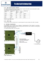
Figure 2 Connector position on PCB
Internal power supply (3.3 V)
If the green "3.3V" LED is illuminated, the internal power supply has been established.
4.1.2 Relay
One LED is positioned in front of each relay to indicate the relay status. The LED illuminates when a relay is
energized.
Relay activated
Modbus activity
Master - Slave
Display ECD-05
Short-circuit proof output
(future use)
EXV
Synchronized defrost
Modbus Master COM
(future use)
Modbus Slave COM
Modbus Slave COM
Safety Relay
Relay 8
Relay 7
Relay 6
Relay 5
Relay 4
Relay 3
Relay 2
Relay 1
Alarm relay
Power supply
D
is
c
h
.
P
S
u
c
.
P
S
u
c
.
T
/
Fin
3
T
D
is
c
h
.
T
/
Fin
2
T
C
a
b
ine
t
T
Fin
T
A
ir Ou
t
T
A
ir I
n
T
H
P
s
w
it
c
h
L
P
s
w
it
c
h
D
igit
a
l
In
p
u
t
1
D
igit
a
l
In
p
u
t
2


