TM
10
Installation Operation & Maintenance manual ELQ
DOC.55.EDN Rev: E
October 2012
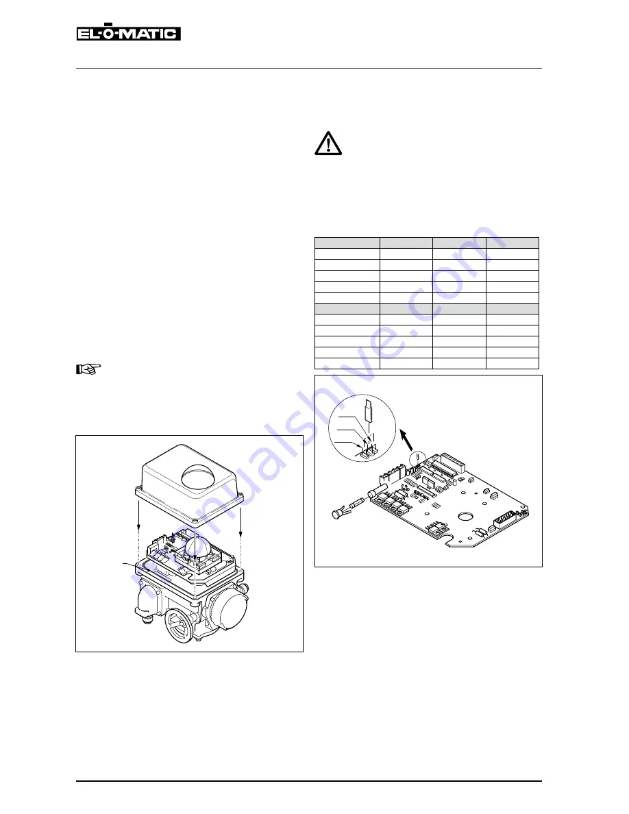
Jp1
Jp2
Jp3
1
"Closed" position:
7. Move the valve to about 15° before the fully
“closed” position with the manual override hand
wheel.
8. Turn the “closed” mechanical stop screw out
(CCW) 4 turns.
9. Move the valve to the fully closed position with
the manual override hand wheel.
10. Turn “Motor switch closed”-cam (CCW) until
switch trips.
For position indication set the limit switches as
follows:
Turn “Motor switch closed”-cam (CCW) until
switch trips.
11. Turn the “Closed” mechanical stop screw in (CW)
until an obstruction is felt (do not force) then
back-off 3 turns and lock the mechanical stop
screw with the locknut.
Important
•
After adjustments always mount the cover to
the housing or continue with chapter 5.
•
Take care that the cover seal is in place to
comply to dust and water tightness according
to IP65, IP67 or NEMA4.
4.2
torque setting
4.2.1 Jumper setting maximum torque
Warning
Be sure that the jumper is placed at one of
the three jumper positions.
The ELQ is factory set at its maximum output torque.
The output torque can be reduced by means of a
jumper (see table 4.2).
table 4.2 jumper setting maximum torque
Metric data
jp1
jp2
jp3
ELQ 100
100 Nm.
80 Nm.
55 Nm.
ELQ 200
200 Nm.
160 Nm.
130 Nm.
ELQ 300
300 Nm.
250 Nm.
210 Nm.
ELQ 500
500 Nm.
430 Nm.
360 Nm.
ELQ 800
800 Nm.
700 Nm.
600 Nm.
Imperial data
ELQ 100
885 In.Ibf
708 In.Ibf
487 In.Ibf
ELQ 200
1770 In.Ibf
1416 In.Ibf
1151 In.Ibf
ELQ 300
2655 In.Ibf
2213 In.Ibf
1859 In.Ibf
ELQ 500
4425 In.Ibf
3806 In.Ibf
3186 In.Ibf
ELQ 800
7081 In.Ibf
6196 In.Ibf
5310 In.Ibf
4.1.1 Mount cover


