TM
13
Installation Operation & Maintenance manual ELQ
DOC.55.EDN Rev: E
October 2012
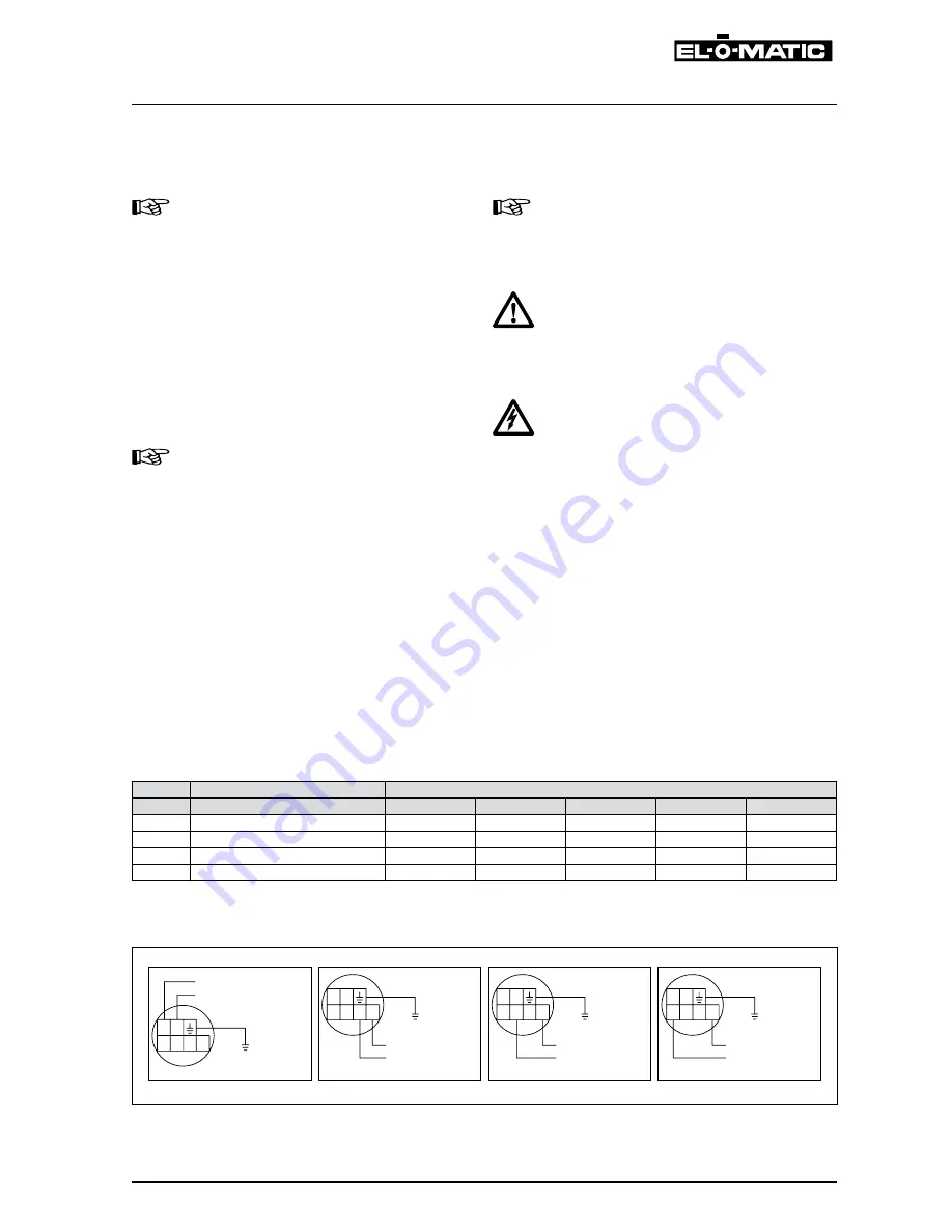
6.1.1 Power supply terminals
5
3 2 1 0
4
5
3 2 1 0
4
5
3 2 1 0
4
N 115 VAC
50/60Hz
(+10% / -6%)
L1
N 230 VAC
50/60Hz
(+10% / -6%)
L1
24 VDC (+10%)
+
-
400 VAC
50/60Hz
(+10% / -6%)
L2
L1
5
3 2 1 0
4
Note
-
Before connecting the power supply connect
all options properly (see option instructions).
-
Ground properly.
-
When supplying three phase current connect
a maximum of three wires, two phases and
earth.
-
Use and mount cable glands or blindplugs as
required by national or local legislation.
-
When IP65, IP67 or NEMA4X ingress protec
-
tion is required, the electrical entries must be
fitted with equivalent or higher rated glands
or blindplugs.
AtEX Installation instructions
-
See chapter 1.2 for use of Flameproof ELQ
actuators in ATEX classified hazardous ar
-
eas.
requirement for Factory Mutual (FM)
The 24 VDC power supply has to be protect
-
ed by a power limited circuit (< 30 VDC and
max. 150 W).
Warning
The actuator should be externally protected
by a fuse.
AC: Fuse min. 2.5 Amp.
DC: Fuse min. 10 Amp.
Warning
When power is supplied on for instance ter
-
minals, 4 and 5 (for 24VDC), then the other
terminals will output their respective (high)
voltage.
6.1
Power supply specification
The power print is designed so that four basic types of power can be supplied to the actuator (see table 6.1
and figure 6.1.1)
Table 6.1 Power supply specification
terminal Voltage range
Maximum current *
ELQ-100
ELQ-200
ELQ-300
ELQ-500
ELQ-800
0 - 1
115 VAC (+10% /-6%) 50/60 Hz
1 A
1 A
1 A
1.7 A
1.7 A
0 - 2
230 VAC (+10% /-6%) 50/60 Hz
0.5 A
0.5 A
0.5 A
0.9 A
0.9 A
0 - 3
400 VAC (+10% /-6%) 50/60 Hz
0.3 A
0.3 A
0.3 A
0.5 A
0.5 A
4 - 5
24 VDC (+10%)
4.1 A
4.3 A
4 A
5.3 A
5.1 A
*
Max. current when all options mounted and under full load.
6
CONNECtING POWEr SUPPLy
Wiring dimensions for power and earth connection: Max. 2.5mm
²
/ 14 AWG. Tightening torque: 0.8Nm / 7 in/lb.


