TM
17
Installation Operation & Maintenance manual ELQ
DOC.55.EDN Rev: E
October 2012
9
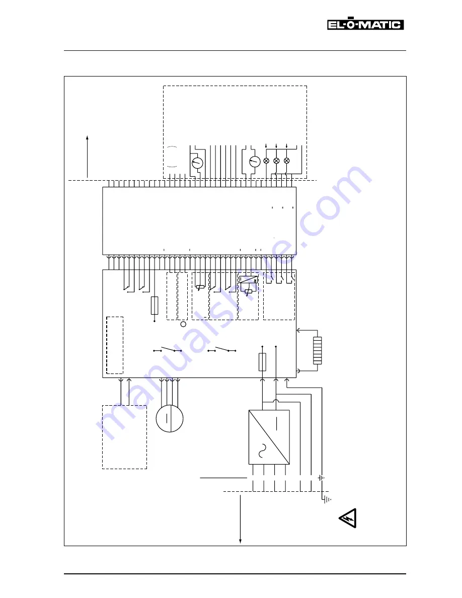
WIrING DIAGrAM
+
-
4-20 mA
0-10
VD
C
RS232
4-20 mA
+
-
-
+
400
V
230
V
115
V
0
V
+24
VDC
GND
3
2
1
0
5
4
MS
1
MS
2
+24
V
+24
V
GND
+
-
1
2
3
4
5
6
7
8
9
10
11
12
13
14
15
16
17
18
19
20
21
22
23
24
25
26
27
28
29
30
31
32
33
34
35
36
37
M
Field wir
ing
Po
wer supply
Field wir
ing
Control signals
Connector board
OPTION CONNECTIONS
MS1 = motor
sw
itch
“Open”
MS2 = motor
sw
itch
“Closed”
The motor stops when motor
sw
itch reaches
the opened or closed position.
Electronic Control Unit (ECU)
Optional
: plug in
Speed Control
Connectornr.
Optional
:
Local Control Statio
n
functions:
Po
wer supply
Remot
e
Local open
Local close
Of
f
brak
e
Open - connect 24VD
C
Close - connect 24VD
C
Common
Limit Switch closed COM
Limit Switch closed NC
Limit Switch closed NO
Limit Switch open COM
Limit Switch open NC
Limit Switch open NO
+ 24V Output
GND Output
I in
+
I in
-
Communication lin
e
Communication lin
e
Po
tmeter
+
Po
tmeter
va
r.
Po
tmeter
-
Extra limit Switch 3 COM
Extra limit Switch 3 NC
Extra limit Switch 3 NO
Extra limit Switch 4 COM
Extra limit Switch 4 NC
Extra limit Switch 4 NO
Po
sition
Tr
ansmitter
+
Po
sition
Tr
ansmitter
-
Status input Motor r
unning
Status output
Status input Supply control
Status output
Status output
Status input Local contro
l
Heater 10W
Optional
Status
Module
Optional
Po
sition
Tr
ansmitter
Optional
Extra Limit
Switches
Optional
Po
tentio-
meter
10kOhm
B
Optional
Communication
Optional
Po
sitioner
Fuse
max.
500m
A
CO
M
NC
“Open”
Switc
h
NO
CO
M
NC
“Closed”
Switc
h
NO
Input
24VDC Input
V
max.
30
VDC Input
Motor Running
Po
wer supply connected
ELQ
sw
itched to
Local control station
0-30V DC /
AC
Output
Fuse
max.
10
A
Wa
rnin
g
When po
wer is supplied on
fo
r instance te
rm
inal
s,
4 and 5 (f
or 24VDC), then the other te
rm
inals will
output their respectiv
e (high) v
oltage
.
The ECU contains an electronic torque control
.
Switches are sh
ow
n in the mid position of the stro
ke


