Installation
5.
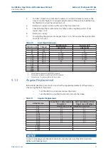
Install the actuator to the bracket. Tighten all bolts and apply the correct torque
(refer to Table 8).
Table 8.
Bottom flange torque values
Actuator Size
ISO Pattern
Torque (Nm)
Torque (lbf.ft)
Thread
Min.
Max.
Thread
Min. Max.
12
F04
M6
4.5
5
10-24UNC
3.3
3.7
25
F03 inner pattern
M5
2.0
3.0
10-24UNC
1.5
2.2
F05 outer pattern
M6
4.5
5.0
1/4"-20
3.3
3.7
40, 65, 100
F05 inner pattern
M6
4.5
5.0
1/4"-20
3.3
3.7
F07 outer pattern
M8
10.5
12.5
5/16"-18
7.7
9.2
150, 200, 350
F07 inner pattern
M8
10.5
12.5
5/16"-18
7.7
9.2
F10 outer pattern
M10
21.0
24.5
3/8"-16
15.5
18.1
600
F10 inner pattern
M10
21.0
24.5
3/8"-16
15.5
18.1
F12 outer pattern
M12
34.5
43.0
1/2"-13
25.4
31.7
950, 1600, 2500,
4000
6.
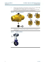
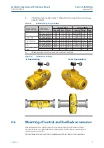
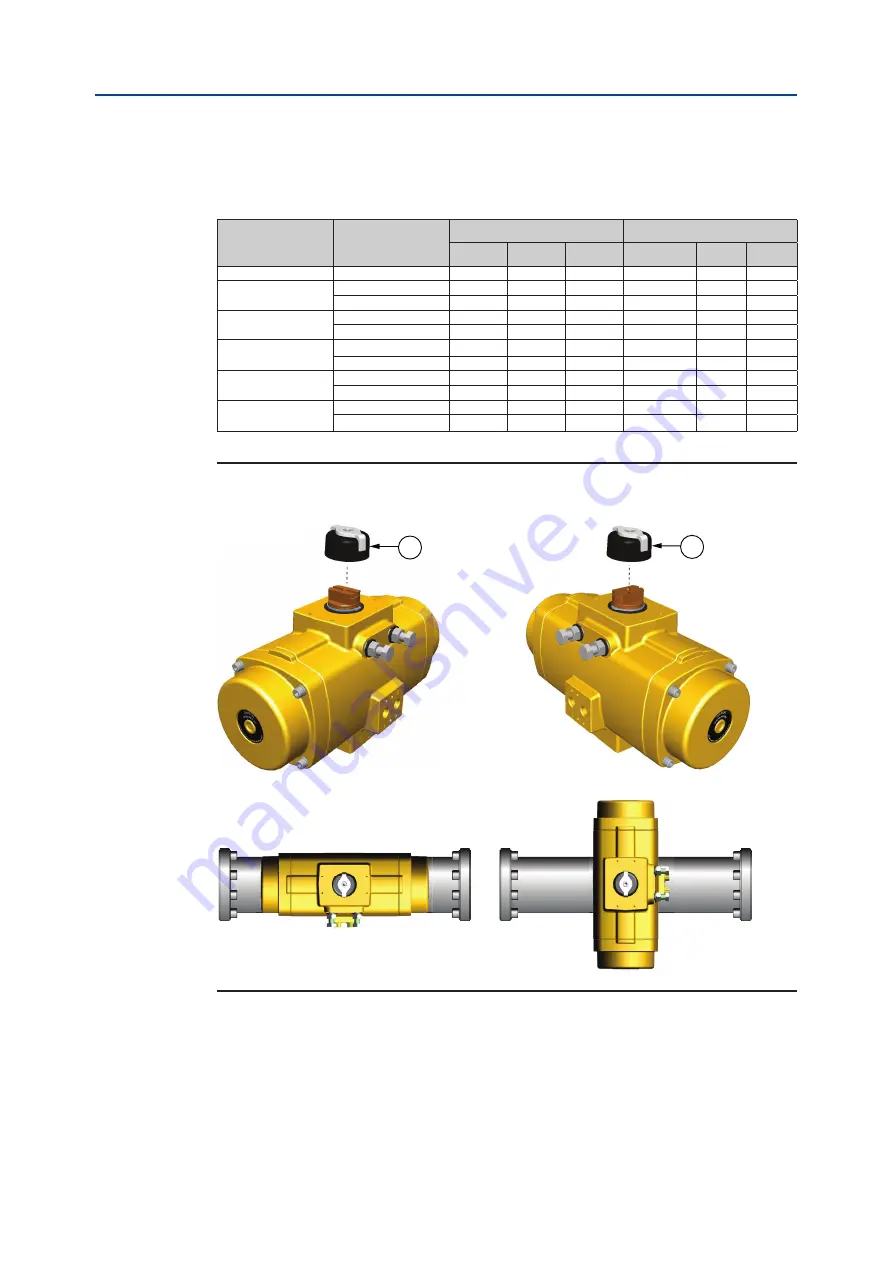
When required, mount or adjust the visual indicator (22).
Figure 12
Indicator mounting
"In Line mounting"
"Across Line mounting"
22
22
4.6
Mounting of control and feedback accessories
Solenoid valve and or switch boxes can now be mounted to the actuator. Check
the instructions as shipped with these components for installation, operating and
maintenance instructions.
We recommend to test-cycle the complete assembly to check correct operation.
Installation, Operation and Maintenance Manual
DOC.IOM.EF.EN Rev. 6
September 2015
15
Section 4: Installation
Summary of Contents for EL-O-Matic F-Series
Page 2: ......


