Mechanical Stroke
3.
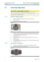
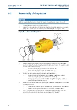
Turn the “closed” stop clockwise to reduce or counterclockwise to increase the
travel. Consult chapter 5.1.3 (angular displacement of the pinion), to define how
far the limit stop must be turned in or out.
4.
Remove air supply. Actuator will move to the closed position.
5.
Check whether the actuator valve assembly is in the required position. If not
repeat steps 1 to 5.
6.
Remove air supply.
7.
For adjusting the open position repeat steps 1 to 6, but now for the open position
and "open" stop (1).
Table 10.
Limit stop dimensions
Actuator size
Thread
Bolt Wrench
Nut wrench
size (mm)
size (mm)
25
M 6
10
10
40
M 8
13
13
65
M 10
17 (16)*
17 (16)*
100
M 10
17 (16)*
17 (16)*
150
M 10
17 (16)*
17 (16)*
200
M 12
19 (18)*
19 (18)*
350
M 16
24
24
600
M 20
30
30
950
1600
2500
4000
1.
Default dimension according DIN933 standard.
2.
Dimensions in brackets according ISO4017 standard.
3.
Actuator size 12 is not available with limit stops.
5.1.3
Angular Displacement
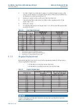
Below table identifies, per actuator size, what the angular displacement of the pinions is,
when using the limit stop screws.
—
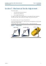
Turn the limit stop clockwise reduces the stroke
—
Turn the limit stop counterclockwise to increase the stroke
Table 11.
Angular Displacement
Actuator size
Turns for 5° adjustment of
the pinion:
360° revolution of limit
stop screw will adjust
F 12
Actuator size 12 is not available with limit stops
F 25
0.7
7.1°
F 40
0.8
6.3°
F 65
0.6
8.3°
F 100
0.7
7.1°
F 150
1.2
4.2°
F 200
1.0
5.0°
F 350
0.8
6.3°
F 600
0.8
6.3°
F 950
F 1600
F 2500
F 4000
NOTICE
In case of air leakage over the limit stop bolts, turn the lock nut of the limit stop bolts
tighter, until leakage stops.
Installation, Operation and Maintenance Manual
DOC.IOM.EF.EN Rev. 6
September 2015
19
Section 5: Mechanical Stroke
Summary of Contents for EL-O-Matic F-Series
Page 2: ......


