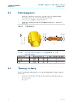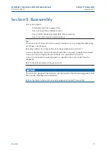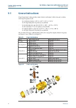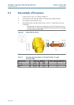
Reassembly
9.4
Reassembly and settings of the limit stops
1.
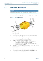
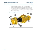
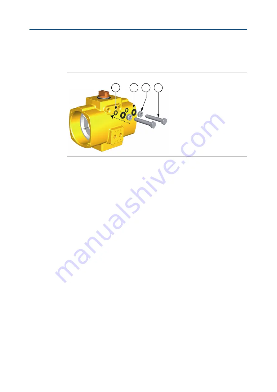
Install the limit stop screws (17), limit stop nuts (18), limit stop washers (19) and
limit stop o-rings (15).
Figure 27
Install Limit Stop Bolts
15
17
18
19
2.
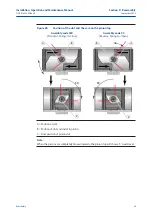
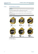
Move the pistons inward until the slot in the top of the pinion is perpendicular to
centerline of the housing.
3.
Double check if the position of the slot and the cam on the pinion top is in the
correct position (see figure 26). Screw in the right hand travel stop until it comes
into contact with the pinion stop face.
4.
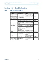
Move the pistons outward until the slot in the top of the pinion is in line with the
centerline of the housing.
5.
Screw in the left hand travel stop until it comes into contact with the pinion stop
face.
—
For accurate travel stop adjustment of the actuator on the valve, see
section 5.
9.5
Reassembly of the end caps
9.5.1
Double-Acting actuators
1.
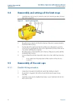
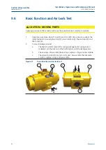
Grease the O-ring seals (14) and B port seals (16) according to step 9.1.
2.
Ensure that O-ring seals (14) and B port seals (16) are kept in place during
assembly.
3.
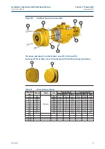
Install the end caps (2) and tighten the end cap screws (10). Refer to Table 14 for
the correct torque.
34
September 2015
Installation, Operation and Maintenance Manual
DOC.IOM.EF.EN Rev. 6
Section 9: Reassembly
Summary of Contents for EL-O-Matic F-Series
Page 2: ......

