Appendix
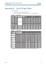
Appendix B: Tool & Torque Table
This section explains:
•
Which tools to use for the indicated fasteners
•
The recommended amount of torque to apply on the indicated fasteners.
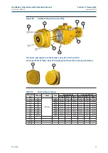
Table B-1.
End cap bolts
Actuator
size
Thread
Tool
Size
Torque (Nm)
Torque (lbf.ft)
Target Min.
Max. Target Min.
Max.
12
M4
Allen key
SW 3
1.1
0.8
1.3
0.8
0.6
1.0
25
M5
SW 4
2.0
1.6
3.0
1.5
1.2
2.2
40
M5
SW 4
2.0
1.6
3.0
1.5
1.2
2.2
65
M5
SW 4
2.0
1.6
3.0
1.5
1.2
2.2
100
M5
SW 4
2.0
1.6
3.0
1.5
1.2
2.2
150
M6
SW 5
3.3
2.6
5.1
2.4
1.9
3.8
200
M6
SW 5
3.3
2.6
5.1
2.4
1.9
3.8
350
M8
SW 6
8.4
6.7
12.2
6.2
4.9
9.0
600
M10
SW 8
15.3
12.2
24.8
11.3
9.0
18.3
950
1600
2500
4000
Table B-2.
Bottom flange
Actuator
size
ISO Pattern
Metric Torque (Nm)
Imperial
Torque (lbf.ft)
Thread Min.
Max.
Thread
Min.
Max.
12
F04
M6
4.5
5.0
10-24UNC
3.3
3.7
25
F03 inner pattern
M5
2.0
3.0
10-24UNC
1.5
2.2
F05 outer pattern
M6
4.5
5.0
1/4"-20
3.3
3.7
40, 65, 100
F05 inner pattern
M6
4.5
5.0
1/4"-20
3.3
3.7
F07 outer pattern
M8
10.5
12.5
5/16"-18
7.7
9.2
150, 200, 350
F07 inner pattern
M8
10.5
12.5
5/16"-18
7.7
9.2
F10 outer pattern
M10
21.0
24.5
3/8"-16
15.5
18.1
600
F10 inner pattern
M10
21.0
24.5
3/8"-16
15.5
18.1
F12 outer pattern
M12
34.5
43.0
1/2"-13
25.4
31.7
950
F10 inner pattern
M10
3/8"-16
F14 outer pattern
M16
5/8"-11
1600
F16 inner pattern
M20
3/4"-10
F25
1
outer pattern
M16
5/8"-11
2500
F16 inner pattern
M20
3/4"-10
F25
1
outer pattern
M16
5/8"-11
4000
F16 inner pattern
M20
3/4"-10
F25 outer pattern
M16
5/8"-11
1. For actuator sizes 1600 and 2500 only 4 holes of the ISO5211 F25 drilling pattern are available.
Installation, Operation and Maintenance Manual
DOC.IOM.EF.EN Rev. 6
September 2015
45
Appendix
Summary of Contents for EL-O-Matic F-Series
Page 2: ......

