PACSystems™ RX3i DNP3 Outstation User Manual
Section 5
GFK-3103B
June 2020
System Operation
57
1.
CROB Control Code
This defines the control code for the CROB Control command as received by the Outstation. The three
bits are used to indicate the control code as shown in Figure 14.
2.
Trigger Bit
This is a read/write bit and is set by the Outstation Module in response to the CROB command from the
master station. This can be reset by the user application to indicate the consumption.
3.
UINT8: Count
This is the number of times the Outstation Module shall execute the operation. Counts greater than
one generate a series of pulses or repeated operations for the point.
4.
UINT16: Pulse Time
This is the duration for the pulse ON time /OFF time expressed as the number of milliseconds, that the
output remains active. The pulse time can be set in 1 ms increments up to 65,536 ms.
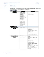
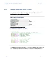
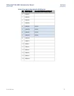
5.5.2
Parameters for CROB Control Block
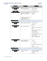
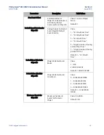
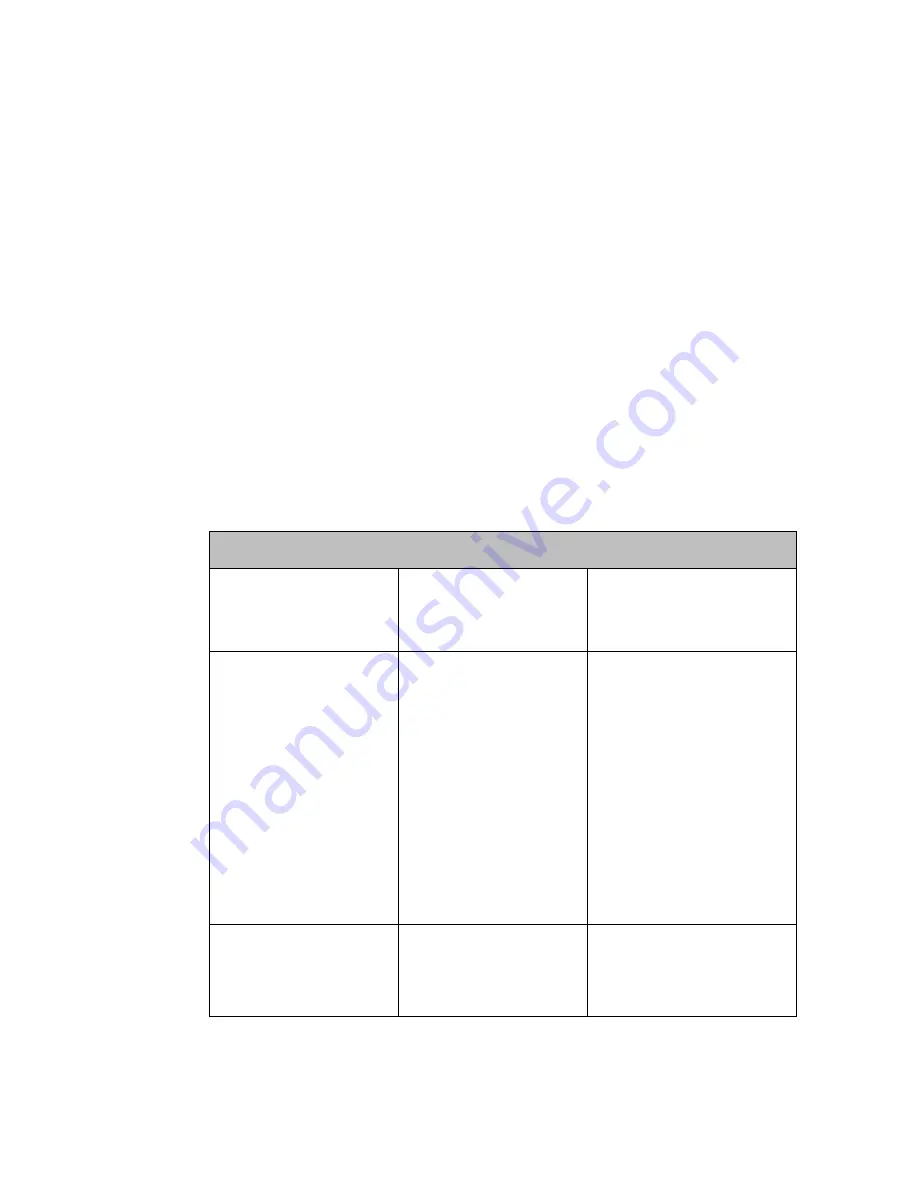
The Parameters for configuring the CROB Control Block are:
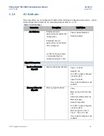
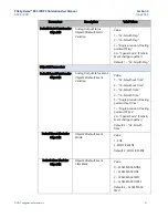
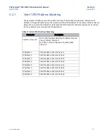
Table 19: Parameters for CROB Control Block
CROB Parameters
Number of Points for
CROB
Number of CROB Points
Value: 0 to 1024 (Should be
<= No. of Obj12 Points)
Default: 0
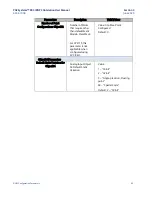
Memory Address for CROB
CPU Reference Memory
Type & Address
Value:
Memory Type: %R, %AI,
%AQ, %W
Allocates available
reference Memory ranges
Default: %R00001
For CPE115 when
configured using SVC_REQ:
Memory Type: 8 - %R, 10 -
%AI, 196 - %W
Start Point Offset
Start Point offset of
Object12 to be
associated with CROB
Control Word
Value: 1 to No. of Obj12
Points
Default: 0
If the “
Number of Points for Obj12
”
parameter is set to 0, then no CROB words are configured
. “Start
Point Offset” parameter is offset/Point Number of Obj12 that needs to
be associated with CROB
Control DWord.

