background image

PACSystems™ RX3i DNP3 Outstation User Manual


Section 1 

GFK-3103B 


June 2020 


Introduction 


Section 1


 Introduction 

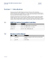
This document describes DNP3 Outstation protocol over Ethernet on PACSystems RX3i 
IC695CPE400/CPL410 and RSTi-EP EPSCPE115 controllers. This feature enables CPE400/CPL410 and 
CPE115 controllers to act as a DNP3 Outstation on a DNP3 Network, which permits controller data to 
be exchanged with the DNP3 Masters on a given network.  

Introductory material may be found in this Chapter. Chapter 2 provides the mechanism to configure 
the DNP3 Outstation on this controller. Chapter 3 provides the details of configuration parameters. 
Chapter 4 describes HSB Redundancy configuration. Chapter 5 describes system operation. Chapter 6 
provide performance data for DNP3 Outstation. Appendix provides a profile of the DNP3 Outstation. 


1.1


DNP3 Outstation Compatible Controllers 

Catalog Number 

Description 

IC695CPE400 

RX3i 1.2GHz 64MB Rackless CPU w/Field Agent 

IC695CPL410 

RX3i 1.2GHz 64MB Rackless CPU w/Linux 

EPSCPE115 

RSTi-EP 1.0GHz 1.5MB Rackless CPU 


1.2


Revisions in this Manual 

Rev 

Date 

Descriptions 

June 2020 

Updates with regard to CPE115 and its use of the DNP3 
protocol  

Jan 2020 

Initial Release 


Summary of Contents for EPSCPE115

Page 1: ...USER MANUAL GFK 3103B June 2020 PACSystems DNP3 Outstation USER MANUAL ...

Page 2: ...ion Objects and Variance support 9 1 9 2 DNP3 Outstation Static and Event Poll Support 11 1 9 3 Number of Points and Events Support 11 Section 2 Configuration of DNP3 Outstation 13 2 1 Required Configuration Tools 13 2 2 Configuration 14 2 2 1 Project Creation and Configuration 14 2 2 2 Ethernet IP Address Configuration 16 2 2 3 Enable DNP3 Outstation 17 2 2 4 DNP3 General Settings and Object Attr...

Page 3: ...em Operation 51 5 1 Controller and DNP3 Outstation Communication 52 5 2 Strict Connection Control Parameters 52 5 2 1 Strict TCP IP Address Matching 53 Validate Source IP 53 5 2 2 Strict Lower Level Address Matching 54 5 3 Event Buffer Configuration 54 5 4 Sequence of Events SOE 55 5 5 CROB Control Feature 56 5 5 1 CROB Control Definition 56 5 5 2 Parameters for CROB Control Block 57 5 5 3 Example...

Page 4: ...n using Service Request 76 5 14 6 Service Request Sub function SLAVE_STATUS 0x03 76 5 14 7 Service Request Sub function CONFIG_STATUS 0x04 78 5 14 8 Service Request Sub function SEND_POINT_PUSH_DATA 0x05 79 5 14 9 Point Push Data Example 80 5 14 10 Service Request Sub function SOE_ENABLE_DISABLE_MASK 0x06 83 5 15 I O Scans 84 5 16 Alarms 84 5 17 Station Manager 85 Section 6 CPU Performance Calcula...

Page 5: ...6 Figure 12 Enable DNP3 Configuration 17 Figure 13 DNP3 General Settings Parameters 18 Figure 14 DNP3 Object Attributes Parameters 19 Figure 15 CROB Control DWord Layout 56 Figure 16 CROB Control DWord Layout 58 Figure 17 CROB Control DWord Layout for CPE115 58 Figure 18 Configuration example for Analog Inputs polled object 62 Figure 19 CPE115 Configuration example for Analog Inputs polled object ...

Page 6: ...ample Configuration for CROB Control 59 Table 21 Header Section of the Record Format 60 Table 22 Record Section may repeated up to 8 times 61 Table 23 Example of Memory Layout when Obj30 variation set to 44 Special Code 63 Table 24 Point Index and its assignments 65 Table 25 Point Index Assignments 68 Table 26 Quality Force State Table 69 Table 27 SERVICE_REQUEST 130 Protocols 71 Table 28 SERVICE_...

Page 7: ...to be met during installation operation and maintenance The information is supplied for informational purposes only and Emerson makes no warranty as to the accuracy of the information included herein Changes modifications and or improvements to equipment and specifications are made periodically and these changes may or may not be reflected herein It is understood that Emerson may make changes modi...

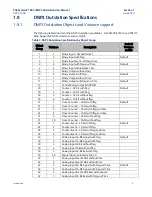
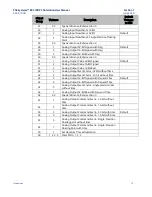
Page 8: ... provides the mechanism to configure the DNP3 Outstation on this controller Chapter 3 provides the details of configuration parameters Chapter 4 describes HSB Redundancy configuration Chapter 5 describes system operation Chapter 6 provide performance data for DNP3 Outstation Appendix provides a profile of the DNP3 Outstation 1 1 DNP3 Outstation Compatible Controllers Catalog Number Description IC6...

Page 9: ...ault CROB Data Object A Control Relay Output Block Data Object Group 12 Variance 1 is the method used to set a bit in the PLC from a Master Station It represents a physical action of Select Before Operate SBO for an Outstation to set a bit over DNP3 DNP Distributed Network Protocol DNP3 Specific implementation of DNP Flags Indicators that are returned to the Master Station from the Outstation in g...

Page 10: ...a change then time stamping each change for the purpose of establishing the sequence in which the changes were detected TCP IP The Transmission Control Protocol TCP is one of the core protocols of the Internet Protocol suite IP and is so common that the entire suite is often called TCP IP TCP provides reliable ordered and error checked delivery of a stream of octets between programs running on com...

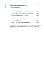
Page 11: ...ecure Deployment Guide GFK 2830 PACSystems Hot Standby CPU Redundancy User Manual GFK 2308 PACSystems RX3i and RSTi EP CPU Programmer s Reference Manual GFK 2950 PACSystems Hot Standby CPU Redundancy User s Guide GFK 2308 PACSystems RX3i System Manual GFK 2314 PACSystems RSTi EP Controllers Performance Evaluation Manual GFK 3086 In addition to these manuals datasheets and product update documents ...

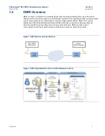
Page 12: ...d to other vertical markets such as water waste water transportation and oil and gas pipeline sectors DNP3 is the current specification of Distributed Network Protocol DNP which has a long history of being a Remote Terminal Unit RTU protocol based on a 3 layer protocol scheme DNP3 provides a set of communications protocols used between components in process automation systems Figure 1 DNP3 Basic S...

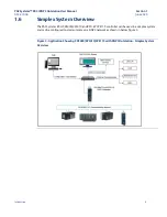
Page 13: ...implex System Overview The PACSystems RX3i CPE400 CPL410 and RSTi EP CPE115 controller can be used in a simplex system and can be configured to communicate on a DNP3 network as shown in below Figure 3 Figure 3 Application Showing CPE400 CPL410 CPE115 with DNP3 Outstation Simplex System Overview ...

Page 14: ...Overview The PACSystems RX3i CPE400 CPL410 controller can be used in an HSB system and can be configured to communicate on a DNP3 network as shown below Figure 4 Note RSTi EP EPSCPE115 does not support HSB Redundancy Figure 4 Application showing RX3i CPE400 CPL410 with DNP3 Outstation HSB System Overview ...

Page 15: ... Operate Direct Operate No Ack 8 Control Relay Output Block CROB Operate command PULSE_ON PULSE_OFF LATCH_ON LATCH_OFF TRIP and CLOSE 9 Analog Output Block AOV Operate command 10 Analog input reporting Deadband 11 Linear and Circular Event Buffer Configuration for storing the Sequence of events 12 Configurable Data Link Layer confirmation Never Only for multi frame messages or Always 13 Configurab...

Page 16: ...6 bit with flag 20 5 Counter 32 bit without flag 20 6 Counter 16 bit without flag 21 1 Frozen Counter 32 bit with flag Default 21 2 Frozen Counter 16 bit with flag 21 5 Frozen Counter 32 bit with flag and time 21 6 Frozen Counter 16 bit with flag and time 21 9 Frozen Counter 32 bit without flag 21 10 Frozen Counter 16 bit without flag 22 1 Counter Event 32 bit with flag Default 22 2 Counter Event ...

Page 17: ...g Output Value 32 Bit Real 42 1 Analog Output Event Status 32bit without time 42 2 Analog Output Event Status 16 bit without time 42 3 Analog Output 32 Bit Signed with Flag and Time Default 42 4 Analog Output 16 Bit Signed with Flag and Time 42 5 Analog Output Event Status single precision real without time 42 7 Analog Output 32 Bit Real with Flag and Time 42 44 Special Variance Refer section 0 43...

Page 18: ...nary Input 1 3000 1024 Binary Output Status 10 3000 1024 Binary Counters 20 3000 1024 Frozen Counters 21 3000 1024 Analog Input 30 2000 2000 Analog Output Status 40 2000 2000 Analog Deadband 34 2000 2000 Binary Command Control Relay Output Block CROB 12 1024 1024 Analog Output Value 41 1000 1000 Table 3 Event Data Objects Event Object Group Maximum Events Binary Input Event 2 8000 Binary Output Ev...

Page 19: ... CPL410 and CPE115 2 1 Required Configuration Tools CPE400 CPL410 PACSystems RX3i CPU CPE400 CPL410 Firmware version 9 95 or later PAC Machine Edition configuration and programming software version 9 70 or later CPE115 SVC_REQ PACSystems RSTi EP CPE115 Firmware version 9 97 or later PAC Machine Edition configuration and programming software version 9 70 or later PME GUI PACSystems RSTi EP CPE115 F...

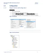
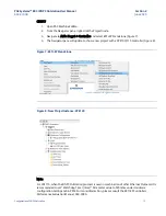
Page 20: ...reation and Configuration CPE400 CPL410 1 Open PAC Machine Edition 2 From the Navigator pane right click the Project node 3 Navigate to Add a Target Controller and select PACSystems RX3i Rackless Figure 6 4 The Navigator pane will update to show a new project with a CPE400 CPL410 controller Figure 5 RX3i Rackless Figure 6 New Project Instance ...

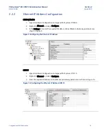
Page 21: ...4 The Navigator pane will update to show a new project with a CPE100 115 controller Figure 8 Figure 7 RSTi EP Standalone Figure 8 New Project Instance CPE100 Note For CPE115 when the DNP3 Outstation protocol is used in combination of other Ethernet Protocols it is recommended to set Watchdog Timer msec Parameter value to 500mSec under Hardware configuration Settings tab in PME For more information...

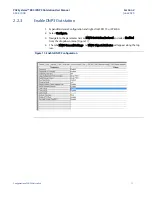
Page 22: ...k Ethernet and select Configure 3 In the Settings tab enter the required IP address Subnet Mask and Gateway parameters as shown in Figure 9 Figure 9 Configuring the Ethernet IP Address CPE115 1 Expand Hardware Configuration and expand PACSystems CPE115 2 Right click Ethernet and select Configure 3 Enter the required IP address Subnet Mask and Gateway parameters as shown in Figure 10 Figure 10 Conf...

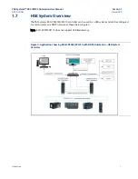
Page 23: ...utstation 1 Expand Hardware Configuration and right click CPE115 or CPE400 2 Select Configure 3 Navigate to the parameter named DNP3 Outstation Protocol and select Enabled from the dropdown menu Figure 11 4 The tabs DNP3 General Settings and DNP3 Object Attributes will appear along the top row Figure 11 Enable DNP3 Configuration ...

Page 24: ...tings and Object Attributes Configuration Use the tabs DNP3 General Settings and DNP3 Object Attributes to configure the DNP3 Outstation For a detailed description of each parameter see Section 3 Alternatively with the field in question selected use the F1 key to toggle PME s Help Companion Figure 12 DNP3 General Settings Parameters ...

Page 25: ...PACSystems RX3i DNP3 Outstation User Manual Section 2 GFK 3103B June 2020 Configuration of DNP3 Outstation 19 Figure 13 DNP3 Object Attributes Parameters ...

Page 26: ...layer Confirm Mode mDNP3_Setup 15 4 mDNP3_Setup 15 5 Multi Fragment Response mDNP3_Setup 15 6 Multi Fragment Confirm mDNP3_Setup 15 7 Class Mask None mDNP3_Setup 15 8 Unused bit mDNP3_Setup 15 9 Link Timeout Disconnect mDNP3_Setup 15 10 Delete Oldest Events mDNP3_Setup 15 11 Enable Point push Events Local Forced Flag mDNP3_Setup 15 12 Enable Point push Event Y2k Ladder mDNP3_Setup 15 13 Force DI P...

Page 27: ...on for Object10 mDNP3_Setup 49 Default Event Variation Object11 mDNP3_Setup 50 Default Event Mode Object11 mDNP3_Setup 51 Default Class Mask Object11 mDNP3_Setup 52 Maximum Events Object11 mDNP3_Setup 53 Number of Points for Object 12 mDNP3_Setup 54 Memory Type for Object 12 mDNP3_Setup 55 Memory Address for Object 12 mDNP3_Setup 56 Command Variation for Object 12 mDNP3_Setup 57 Number of Points f...

Page 28: ...85 Default Event Variation Object43 mDNP3_Setup 86 Default Event Mode Object43 mDNP3_Setup 87 Default Class Mask Object43 mDNP3_Setup 88 Maximum Events Object43 mDNP3_Setup 89 Validate Source IP mDNP3_Setup 90 IP Address 1 mDNP3_Setup 91 mDNP3_Setup 92 mDNP3_Setup 93 mDNP3_Setup 94 IP Address 2 mDNP3_Setup 95 mDNP3_Setup 96 mDNP3_Setup 97 mDNP3_Setup 98 IP Address 3 mDNP3_Setup 99 mDNP3_Setup 100 ...

Page 29: ... Validate Source Address mDNP3_Setup 123 Source Address 1 mDNP3_Setup 124 Source Address 2 mDNP3_Setup 125 Source Address 3 mDNP3_Setup 126 Source Address 4 mDNP3_Setup 127 Source Address 5 mDNP3_Setup 128 Source Address 6 mDNP3_Setup 129 Source Address 7 mDNP3_Setup 130 Source Address 8 mDNP3_Setup 131 Reserved mDNP3_Setup 132 Reserved Refer Appendix C for ST Block example to configure DNP3 Outst...

Page 30: ...rvice request 1 Set the required ST Block configuration parameters for DNP3 Outstation 2 Navigate to the Target button on the ribbon bar and select Connect This action will connect toggle the online connection with the target CPU 3 Next select Download the to download the Hardware Configuration to CPU 4 Use SVC_REQ 130 start DNP3 Outstation protocol to begin accepting the DNP3 Master connections F...

Page 31: ...network The PME configuration outlined in this chapter is used for this purpose See Appendix B DNP3 Outstation Device Profile for full support of applicable DNP3 Outstation parameters 1 DNP3 General Settings 2 DNP3 Object Attributes This section will also help users determine how the Outstation Module will be expected to interact with its DNP3 Master s The Outstation Module may be expected to inte...

Page 32: ... IPs are not validated and can establish the connections with Outstation In HSB Configuration this value is always Enabled Refer Section 5 2 1 Value Enabled Disabled Default Disabled for Simplex always Enabled for HSB Note HSB configuration is applicable only for CPE400 CPL410 IP Addresses 1 to 8 Master IP Addresses that a given Master can establish a connection with Outstation Value Valid IP addr...

Page 33: ... to 11 for respective number of Masters Transmit Fragment Size bytes Maximum value of Transmit Fragment Size For e g if configured as 1024 then Outstation will transmit messages with Fragment size of 1024 bytes Value 1 to 2048 Bytes Modulus of 128 Default 2048 Bytes Multi Fragment Response If set to True DNP3 Application layer is allowed to send Multi Fragment responses from Outstation to Master I...

Page 34: ...3 Outstation will set the Need Time IIN bit at startup and after the clock valid period has elapsed Note When SNTP is configured in the CPU this parameter should be set to False Refer Section 5 9 Value True False Default False For CPE115 when configured using SVC_REQ Value 1 0 Outstation Restart Bit Specifies if required to set Restart Bit in IIN when DNP3 Outstation starts Value True False Defaul...

Page 35: ...ing SVC_REQ Value 1 0 Force AO Points to Point Push All the points of the AO Object by default is set in Point Push mode disabling automatic detection of data Refer Section 5 6 2 Value True False Default False For CPE115 when configured using SVC_REQ Value 1 0 Enable Point Push Events Local Forced Flag Specifies whether the DNP3 Outstation will force Point Push Events to Set Re Set the LOCAL FORCE...

Page 36: ...L response is sent to configured Source LLA Address Value Valid LLA In Range of 1 to 65519 Default 3 Maximum Retries Specifies maximum number of link layer retries if link layer confirm times out Value 0 to 255 Default 3 Confirm Mode Specifies when DNP3 Outstation shall ask for link layer confirmations Value Never Always and Sometimes Default Never For CPE115 when configured using SVC_REQ Use mDNP...

Page 37: ...solicited retries before changing to the OFFLINE Value 1 to 255 Default 3 Retry Delay Sec Specifies the time to delay after an unsolicited confirm timeout before retrying the unsolicited response Value 5 to 32000 Sec Default 5 Sec Offline Retry Delay Sec Specifies the time to delay after an unsolicited timeout before retrying the unsolicited response after Maximum Retries have been attempted Set t...

Page 38: ...leted in Session x when a new event is added to an event queue that is full If set to False event with the latest timestamp will be discarded in Session x when a new event is added to an event queue that is full Value True False Default False Note For CPE115 when configured using SVC_REQ there is only single parameter for this feature and it is applicable for all the configured sessions Data Chang...

Page 39: ...s same as configured for Binary Inputs Obj01 Set the configuration parameter values as required by the DNP3 application Digital Output Status Digital Output Status is defined as a DNP3 Object Binary Output Status Obj10 Corresponding PLC memory type memory address and number of Points are required to be configured Set the configuration parameter values as required by the DNP3 application Digital Ou...

Page 40: ...ll 2 CLASS MASK ONE Events generated are categorized as Class 1 Events 3 CLASS MASK TWO Events generated are categorized as Class 2 Events 4 CLASS MASK THREE Events generated are categorized as Class 3 Events All the Events can be classified under Class 0 or Class 1 2 or 3 Events from individual Classes can be polled different intervals as needed by DNP3 Master Number of Point Configurations DNP3 ...

Page 41: ...d Class Mask Type 1 If this parameter is configured as 0 No points in the DNP3 object will participate in Point Template Configuration and have default configured values of Event Mode and Class Mask type 2 If it is configured as non zero then user will be provided with Point Template Configuration Tab with configured value rows where users can choose DNP3 Object type and range of Points with Start...

Page 42: ...t applicable for SVC_REQ configuration Value Enabled Disabled Default Enabled Object01 Parameters Number of Points Object01 Number of Points Value 1 to 3000 Default 100 For CPE115 Value 1 to 1024 When configured using SVC_REQ Value 0 to 1024 If set to 0 DI Attributes is not available Memory Address for Object01 CPU Reference Memory Type Address Memory Type I Q M T G Allocates available reference M...

Page 43: ...ss Mask Object02 Object02 Default Event Class Mask Value 0 CLASS MASK NONE 1 CLASS MASK ONE 2 CLASS MASK TWO 3 CLASS MASK THREE Default 1 CLASS MASK ONE Maximum Events Object02 Maximum Number of Events for Event Object02 Value 0 to 8000 Default 500 Number of Point Configurations Object02 Number of Points that require other than default Event Mode Class Mask For CPE115 this parameter is not applica...

Page 44: ...Variation Value 1 32 bit with Flag 2 16 bit with Flag 5 32 bit with Flag Time 6 16 bit with Flag Time 9 32 bit without Flag 10 16 bit without Flag Default 1 32 bit with Flag Default Event Variation Object22 Binary Counter Event Object22 default Event Variation Value 1 32 bit with Flag 2 16 bit with Flag 5 32 bit with Flag Time 6 16 bit with Flag Time 9 32 bit without Flag 10 16 bit without Flag De...

Page 45: ...n 3 GFK 3103B June 2020 DNP3 Configuration Parameters 39 Parameters Description Valid Values 2 CLASS MASK TWO 3 CLASS MASK THREE Default 3 CLASS MASK THREE Maximum Events Object22 Maximum Number of Events for Event Object22 Value 0 to 8000 Default 500 ...

Page 46: ... not applicable when configured using SVC_REQ Value Enabled Disabled Default Enabled Object10 Parameters Number of Points for Object10 Number of Points Value 1 to 3000 Default 100 For CPE115 Value 1 to 1024 When configured using SVC_REQ Value 0 to 1024 If set to 0 DO Attributes is not available Memory Address for Object10 CPU Reference Memory Type Address Value Memory Type I Q M T G Allocates avai...

Page 47: ... default Event Variation Value 1 Event without Time 2 Event with Time Default 2 Event with Time Default Event Mode for Object11 Object11 default Event Mode Value 1 SOE 2 MOST RECENT Default 2 MOST RECENT Default Class Mask for Object11 Object11 default Event Class Mask Value 0 CLASS MASK NONE 1 CLASS MASK ONE 2 CLASS MASK TWO 3 CLASS MASK THREE Default 1 CLASS MASK ONE Maximum Events for Object11 ...

Page 48: ...12 CPU Reference Memory Type Address Value Memory Type I Q M T G Allocates available reference Memory ranges Default Q 00105 For CPE115 when configured using SVC_REQ Memory Type 70 I 72 Q 76 M 74 T 86 G CROB Parameters Number of Points for CROB Number of CROB Points Value 0 to 1024 Should be No of Obj12 Points Default 0 Memory Address for CROB CPU Reference Memory Type Address Value Memory Type R ...

Page 49: ...d the AI parameters are not allowed to be configured For CPE115 this parameter is not applicable when configured using SVC_REQ Value Enabled Disabled Default Enabled Object30 Parameters Number of Points for Object30 Number of Points Value 1 to 2000 Default 100 For CPE115 when configured using SVC_REQ Value 0 to 2000 If set to 0 AI Attributes is not available Memory Address for Object30 CPU Referen...

Page 50: ...ect32 Analog Input Event Object32 Default Event Variation Value 1 32 bit without Time 2 16 bit without Time 3 32 bit with Time 4 16 bit with Time 5 Single precision Floating point without Time 7 Single precision Floating point with Time 44 Special Code Static Event shall go together Default 3 32 bit with Time Default Event Mode for Object32 Object32 Default Event Mode Value 1 SOE 2 MOST RECENT Def...

Page 51: ... Number of Points that require other than default Event Mode Class Mask For CPE115 this parameter is not applicable when configured using SVC_REQ Value 0 to Max Point Configured Default 0 Object34 Parameters Default Static Variation for Object34 Analog Input Object 34 Default Static Variation Value 1 16 bit 2 32 bit 3 Single precision Floating point 44 Special Code Default 2 32 bit ...

Page 52: ... Disabled the AO parameters are not allowed to be configured For CPE115 this parameter is not applicable when configured using SVC_REQ Value Enabled Disabled Default Enabled Object40 Parameters Number of Points for Object40 Maximum Number of Points Value 1 to 2000 Default 100 For CPE115 when configured using SVC_REQ Value 0 to 2000 If set to 0 AO Attributes is not available Memory Address for Obje...

Page 53: ...ault Event Variation for Object42 Analog Output Status Event Object42 Default Event Variation Value 1 32 bit without Time 2 16 bit without Time 3 32 bit with Time 4 16 bit with Time 5 Single precision Floating point without Time 7 Single precision Floating point with Time 44 Special Code Static Event shall go together Default 3 32 bit with Time Default Event Mode for Object42 Object42 Default Even...

Page 54: ... SVC_REQ Value 0 to Max Point configured Default 0 Object41 Parameters Number of Points for Object41 Maximum Number of Points Value 0 to 1000 Default 0 Memory Address for Object41 Memory Type Address Value Memory Type R AI AQ W Allocates available reference Memory ranges Default AQ00201 For CPE115 when configured using SVC_REQ Memory Type 8 R 10 AI 12 AQ 196 W Command Variation for Object41 Analog...

Page 55: ...on Value 1 32 bit without Time 2 16 bit without Time 3 32 bit with Time 4 16 bit with Time 5 Single precision Floating point without Time 7 Single precision Floating point with Time Default 3 32 bit with Time Default Event Mode for Object43 Object43 Default Event Mode Value 1 SOE 2 MOST RECENT Default 2 MOST RECENT Default Class Mask for Object43 Object43 Default Event Class Mask Value 0 CLASS MAS...

Page 56: ...ttributes tabs Now mirror the configuration to secondary controller NOTE Validate Source IP and Validate Source Address are both enabled by default and users cannot disable these parameters in HSB configuration It is mandatory to provide unique source LLA addresses and Source IPs Configure the Transfer List with a reference memory address ranges provided as part of DNP3 object settings tab under i...

Page 57: ... Controller and DNP3 Outstation Communication Strict Connection Control Parameters Event Buffer Configuration Sequence of Events SOE CROB Control Feature User Event Point Push Interface Special Code Variation 44 Per Point Configuration Clock Valid Period and Time Sync DNP3 Keep Alive DNP3 Flags Quality Force DNP3 Redundancy Feature Analog Deadband DNP3 SVC_REQ 130 commands I O Scans Alarms Station...

Page 58: ...3 Outstation application code is capable of enforcing strict acceptance of connections to the Outstation by DNP3 master stations There are two general parameters which govern this feature and corresponding parameters for setting the incoming connection masks This functionality is also referred to as white listing The Outstation allows the establishment of a white list of allowed connections both T...

Page 59: ...r these parameters as required by the application Table 17 Strict TCP IP Address Matching Parameter Description Validate Source IP Strict TCP IP Address Matching for Master Stations Value Enabled Disabled For CPE115 when configured using SVC_REQ Value 1 0 IP Address 1 Valid IP address Master Station 1 IP Address 2 Valid IP address Master Station 2 IP Address 3 Valid IP address Master Station 3 IP ...

Page 60: ...ble to a maximum of 8000 Events DNP3 Outstation supports 6 Event Objects types Obj 2 11 22 32 42 43 total maximum events available are 48000 In case of CPE115 maximum supported events are 24000 The number of events or size of Event Buffer configured for a given Event object is utilized across all the configured DNP3 master sessions even a single DNP3 master session can result in using up all the e...

Page 61: ...in the DNP3 Outstation whenever Event Mode is set as SOE Events can either be instances of a single point change or multiple changes of the same point The length of the Event Buffer for each individual event object is configurable and maximum buffer size can go up to 8000 events If buffer size is set to 0 then SOE will be disabled and the event object will store only most recent events Once the Ev...

Page 62: ...ke PULSE ON OFF CLOSE TRIP and LATCH ON OFF for the CROB Control objects This is implemented using additional CROB configuration These configurations provide a mechanism for passing on the CROB control information like Control code and Control information coming from the DNP3 Master to the Controller Application logic which can be used for generating desired commands 5 5 1 CROB Control Definition ...

Page 63: ...pressed as the number of milliseconds that the output remains active The pulse time can be set in 1 ms increments up to 65 536 ms 5 5 2 Parameters for CROB Control Block The Parameters for configuring the CROB Control Block are Table 19 Parameters for CROB Control Block CROB Parameters Number of Points for CROB Number of CROB Points Value 0 to 1024 Should be No of Obj12 Points Default 0 Memory Add...

Page 64: ...nd the corresponding effect on memory usage for the CROB Control DWord CPE400 410 CPE115 DNP3 Configuration Using PME GUI Figure 15 CROB Control DWord Layout CPE115 DNP3 Configuration Using SVC REQ Figure 16 CROB Control DWord Layout for CPE115 The mapping below is created per the above given configuration The reference M6005 M6008 will be PLC Controlled CROB objects with associated CROB Control D...

Page 65: ...020 System Operation 59 Table 20 Example Configuration for CROB Control SN CROB Objects Associated CROB Control Dword 0 M6001 1 M6002 2 M6003 3 M6004 4 M6005 R200 5 M6006 R202 6 M6007 R204 7 M6008 R206 8 M6009 9 M6010 10 M6011 11 M6012 12 M6013 13 M6014 14 M6015 15 M6016 ...

Page 66: ...DNP3 Outstation Event Buffer Note A DNP3 point that has been used in the Point Push will not get updated automatically when there is change in the actual reference memory data it can only receive updates using Point Push Interface So care must be taken to use this feature only on the points to have such an intended behavior 5 6 1 Record Format The Point Push Record Format consists first of a 3 Wor...

Page 67: ...ting Tab is set to True all the Points in Obj01 will start in Point Push mode However it takes a single snap shot of all the point values at start up and will not mark the points with changed bit set in the flag This feature can be used when the Point Push interface is being used with the Soft SOE block application to not to detect change of data repeatedly for the same point Similarly use Force D...

Page 68: ...s a maximum of 1200 Points with default data format set as shown below Point Count 44 Special Code Variation Default Static Variation Default Event Variation 300 Analog Input 16 Bit Signed with Flag Analog Input 16 Bit Signed with Flag and Time 300 Analog Input 32 Bit Signed with Flag Analog Input 32 Bit Signed with Flag and Time 600 Analog Input 32 Bit Real with Flag Analog Input 32 Bit Real with...

Page 69: ... Var2 Var 4 Obj 32 Var2 Var 4 32 Bit INT AI601 AI602 300 300 Obj 30 Var1 Var 3 Obj 32 Var1 Var 3 301 Obj 30 Var1 Var 3 Obj 32 Var1 Var 3 302 Obj 30 Var1 Var 3 Obj 32 Var1 Var 3 303 Obj 30 Var1 Var 3 Obj 32 Var1 Var 3 304 Obj 30 Var1 Var 3 Obj 32 Var1 Var 3 305 Obj 30 Var1 Var 3 Obj 32 Var1 Var 3 306 Obj 30 Var1 Var 3 Obj 32 Var1 Var 3 307 Obj 30 Var1 Var 3 Obj 32 Var1 Var 3 Obj 30 Var1 Var 3 Obj 3...

Page 70: ... us to do per point configuration A maximum of 512 points is allowed for a given event Object Users can configure the following parameters on Per Point basis Point Index Index of the Point for which the non default configuration is required This can be configured with values in Range of 0 to Number of Points for Object xx 1 Index values need to be unique and cannot be duplicated Event Mode Event M...

Page 71: ...figuration all the object01 Points will have the following Class Mask Type and Event Mode as shown below Table 24 Point Index and its assignments Point Index Event Mode Class Mask 0 MOST RECENT CLASS MASK NONE 1 and 2 MOST RECENT CLASS MASK ONE 3 SOE CLASS MASK THREE 4 SOE CLASS MASK ONE 5 MOST RECENT CLASS MASK TWO 6 to 8 MOST RECENT CLASS MASK ONE 9 SOE CLASS MASK ONE ...

Page 72: ...figuration In Template Configuration a range of points for selected object can be configured to have different Event Class Mask Type and Event Mode other than the defaults configured at object level Users can configure the following parameters on template basis 1 Object Type Obj2 12 32 42 2 Range of Points Start Point Index End Point Index 3 Event Mode 4 Event Class Mask Type For e g Point Templat...

Page 73: ...ser Manual Section 5 GFK 3103B June 2020 System Operation 67 Figure 20 Template Configuration DI Attributes With the above configuration all the Object02 and Object32 Points will have Class Mask Type and Event Mode as show in Figure 25 ...

Page 74: ...ync Required parameter is Enabled DNP3 Time Sync Required This parameter specifies whether the DNP3 Outstation will set the Need Time IIN bit at Startup and after every clock valid period has elapsed When DNP3 Master sees this bit it responds with a time synchronization message Upon receiving this time synchronization message DNP3 Outstation sets the CPU time This time is used to Time stamp the Ev...

Page 75: ...ress and set its value in runtime logic to interlock quality state with other interlocks 5 12 DNP3 Redundancy Feature The CPE400 CPL410 DNP3 utilizes Redundant IP feature allowing two HSB CPE400 CPL410 controllers to appear as one DNP3 Outstation module DNP3 Redundancy has two CPE400 CPL410 Units in a Hot Standby setup Primary unit and Secondary unit Primary or Secondary status of a unit is decide...

Page 76: ...nts generated for the Analog Input Object30 points An analog input point may use Deadbands to determine when there is a change of input value sufficient to be of interest and report an Event for the change DNP3 Master can set and report the Analog Deadband value for a given Analog Input point When a non zero Analog Deadband value is set for a given Analog Input point and the absolute value of the ...

Page 77: ...REQUEST 130 Protocols Protocol Code OPC UA SERVER 16 0001 DNP3 OUTSTATION 16 0002 Note All other protocol codes other than shown above are reserved and if used the SVC_REQ function will not pass power The DNP3 specific sub functions are shown in below table Table 28 SERVICE_REQUEST 130 Protocol 2 Sub Functions Sub function Code Sub function command Supported by CPU START 16 00 CPE115 STOP 16 01 CP...

Page 78: ...such as SRTP Modbus TCP Client When resuming from STOPPED to READY_TO_START state using a service request the dynamic or run time changes made to the configuration parameters will not be effective To enforce modified configuration data it is mandatory to follow the sequence of STOP CLEAR START commands using service request Table 29 Parameters for START sub function service request Parameter Summa...

Page 79: ...tate It does not remove or clear the configuration files The controller will set the corresponding status bit STOPPED in the DNP3 Outstation status if the command has been handled successfully b When resuming from STOPPED to READY_TO_START state using a service request the changes made to the configuration parameters will not be effective For changes to be effective a CLEAR request must be issued ...

Page 80: ...PACSystems RX3i DNP3 Outstation User Manual Section 5 GFK 3103B June 2020 System Operation 74 ...

Page 81: ...been stopped The controller will set the corresponding status bit CONFIG_STAT_WAITING in the DNP3 Config status if the command has been handled successfully Table 31 Parameters for CLEAR sub function service request Parameter Summary Data Direction LD perspective 16 0002 DNP3 Outstation Protocol IN 16 0002 CLEAR request IN If the SVC_REQ does not pass power it indicates a failure The use of the CL...

Page 82: ...o Run Mode Store of the modified DNP3 configuration ST Block 5 Start DNP3 Outstation using Service Request Sub function command START 0x00 For CPE400 410 this feature is not applicable 5 14 6 Service Request Sub function SLAVE_STATUS 0x03 The SLAVE_STATUS sub function code can be used to obtain 16 bit info about the current state of the DNP3 Outstation The sub function response uses the following ...

Page 83: ...es not pass Power it indicates a failure The SERVER_STATUS word bit definitions are displayed below 1 5 1 4 1 3 1 2 1 1 1 0 9 8 7 6 5 4 3 2 1 0 B A C K U P A C T I V E POINT PUSH IN PROGRESS STOPPED RUNNING READY TO START INIT IN PROGRESS Note While the DNP3 Outstation is starting the SLAVE_STATUS service request returns 0001h DNP3 Outstation Initialization in Progress Example Figure 24 SLAVE_STAT...

Page 84: ...ters for the CONFIG_STATUS sub function service requests Parameter Summary Data Direction LD perspective 16 0002 DNP3 Outstation Protocol IN 16 0004 CONFIG_STATUS request IN 0000 0000 0000 0000 Config Status Response bitmask OUT The use of the CONFIG_STATUS sub function code in a ladder diagram is illustrated in the following example If the SVC_REQ does not pass Power it indicates a failure The CO...

Page 85: ...rs for the SEND_POINT_PUSH_DATA sub function service request Parameter Summary Data Direction LD perspective 16 0002 DNP3 Outstation Protocol IN 16 0005 Send Point Push Data Request IN 107 Words5 of Point Push Data for 8 Records DNP3 Configuration Data IN Note The length of Point Push Data may vary based on the number of Point Push Records The maximum number of point push records supported are lim...

Page 86: ... 8 1 PtPshArrayLL4 3 1 Object type 01 DI 10 DO 30 AIV 40 AOV PtPshArrayLL4 4 0 Variance Typically 0 PtPshArrayLL4 5 17 Point number PtPshArrayLL4 6 Input_Pt Data 0 PtPshArrayLL4 7 0 Data 1 PtPshArrayLL4 8 0 unused PtPshArrayLL4 9 0 unused PtPshArrayLL4 10 2 hour PtPshArrayLL4 11 1 minute PtPshArrayLL4 12 mCountSeq second PtPshArrayLL4 13 4 month PtPshArrayLL4 14 18 day PtPshArrayLL4 15 17 year 2k ...

Page 87: ...k based 5 PtPshArrayLL4 55 30 Object type 01 DI 10 DO 30 AIV 40 AOV PtPshArrayLL4 56 0 Variance Typically 0 PtPshArrayLL4 57 7 Point number PtPshArrayLL4 58 AIV_Var3_1 Data 0 PtPshArrayLL4 59 AIV_Var3_2 Data 1 PtPshArrayLL4 60 0 unused PtPshArrayLL4 61 0 unused PtPshArrayLL4 62 2 hour PtPshArrayLL4 63 1 minute PtPshArrayLL4 64 mCountSeq second PtPshArrayLL4 65 4 month PtPshArrayLL4 66 18 day PtPsh...

Page 88: ...based 8 PtPshArrayLL4 94 40 Object type 01 DI 10 DO 30 AIV 40 AOV PtPshArrayLL4 95 0 Variance Typically 0 PtPshArrayLL4 96 7 Point number PtPshArrayLL4 97 AOV_Var3_1 Data 0 PtPshArrayLL4 98 AOV_Var3_2 Data 1 PtPshArrayLL4 99 0 unused PtPshArrayLL4 100 0 unused PtPshArrayLL4 101 2 hour PtPshArrayLL4 102 1 minute PtPshArrayLL4 103 mCountSeq second PtPshArrayLL4 104 4 month PtPshArrayLL4 105 18 day P...

Page 89: ...e is set to MOST_RECENT The use of the Enable Disable SOE Mode at Runtime sub function code in a ladder diagram is illustrated in the following example If the SVC_REQ does not pass Power it indicates a failure Table 35 Parameters for Enable Disable SOE Mode at Runtime sub function service request Parameter Summary Data Direction LD perspective X8X7X6X5 X4X3X2X1 SOE Channel bitmask for each of 8 ch...

Page 90: ...ne to the DNP3 Master In STOP Mode CROB and Analog Output Values will return a failure to the Master Station RUN IO Disable In RUN IO Disable Mode the DNP3 Outstation will respond as documented for STOP Mode 5 16 Alarms DNP3 Outstation will internally log messages to the CPU log most of these faults are not fatal a given fault may relate to the Ethernet interface or may be specific to the DNP3 Out...

Page 91: ...log Output Status Soe_Ev02 Displays the number of SOE Events generated for Digital Inputs Soe_Ev11 Displays the number of SOE Events generated for Digital Output Status Soe_Ev22 Displays the number of SOE Events generated for Binary Counters Soe_Ev32 Displays the number of SOE Events generated for Analog Inputs Soe_Ev42 Displays the number of SOE Events generated for Analog Output Status Events02 ...

Page 92: ...lays the count of Successful Writes to PLC for AOV Object with Variation 1 AOv1WrEr Displays the count of Failed Writes to PLC for AOV Object with Variation 1 AOv2WrOK Displays the count of Successful Writes to PLC for AOV Object with Variation 2 AOv2WrEr Displays the count of Failed Writes to PLC for AOV Object with Variation 2 AOv3WrOK Displays the count of Successful Writes to PLC for AOV Objec...

Page 93: ...ta which impacts the sweep time of the CPUs In normal operating conditions the impact on sweep time due to DNP3 Event Synchronization is minimal approximately a few milliseconds However if either of the two units is powered down and one unit accumulates DNP3 events then the sweep time of the units will experience an increase in time when the unit powers up This increase in sweep time is due in par...

Page 94: ...ured Events N No of Configured Binary Input DI Events No of Configured Counter Object Events No of Configured Binary Output DO Events No of Configured Analog Input AI Events No of Configured Analog Output AO Events No of Configured Analog Output Value AOV Events This equation only gives an approximate max impact on sweep time and the actual max impact on sweep time may vary slightly from the calcu...

Page 95: ... Application By Emerson Automation Solutions REM All RIGHTS RESERVED REM REM 0x001 INIT_IN_PROGRESS 0x002 READY_TO_START 0x004 RUNNING 0x008 STOPPED 0x100 POINT_PUSH_IN_PROG REM 0x200 ACTIVE UNIT 0x400 BACKUP UNIT REM DNP3Os Application Status 0x204 REM 0x01 WAITING_FOR_CONFIG 0x02 CONFIG_IN_PROGRESS 0x04 CONFIGURED 0x08 INVALID_CONFIG REM DNP3Os Configuration Status 0x04 REM DNP3Os Application St...

Page 96: ...ation for Connection 3 REM This Outstation Session LLA 4 REM Master LLA 3 REM Validation of Master LLA Disabled REM Validation of Master IP Disabled REM Master IP any REM Is session currently active Active REM Session IIN 0x600 REM DNP Connection information for Connection 4 REM This Outstation Session LLA 4 REM Master LLA 3 REM Validation of Master LLA Disabled REM Validation of Master IP Disable...

Page 97: ...at Specifications REM Object 01 REM Memory Type I Bit REM Starting Address 1 REM Number of points 128 REM Def Static Variation 1 REM Object 02 REM Def Event Variation 2 REM Def Event Mode 0 REM Def Class Mask 1 REM Max Event Storage Size 6000 REM Max Point Configs 0 REM Object 20 21 22 not configured REM Object 10 REM Memory Type Q Bit REM Starting Address 1 REM Number of points 128 REM Def Static...

Page 98: ...128 REM Def Static Variation 1 REM Object 43 REM Event Obj43 Count 4 REM Point Offset of AOV Object 41 30 REM Def Cmd Event Variation 3 REM Def Event Mode 1 REM Def Class Mask 3 REM Max Event Storage Size 8000 REM REM REM DNP3S Outstation Option Parameters REM Multiple Data link layer Confirm Mode 0 REM App layer confirmations will be requested REM for non final fragments of a multi fragment respo...

Page 99: ...Soe_Ev42 000001f4H Events02 00000000H Events11 00000000H Events22 00000000H REM Events32 00000000H Events42 00000000H Events43 00000000H Cla1_RBE 00000000H REM Cla2_RBE 00000000H Cla3_RBE 00000000H IIN1_Bit 00000000H IIN2_Bit 00000000H REM IIN3_Bit 00000000H IIN4_Bit 00000000H IIN5_Bit 00000000H IIN6_Bit 00000000H REM IIN7_Bit 00000000H IIN8_Bit 00000000H Ob01RdOK 00025b1aH Ob01RdEr 00000000H REM ...

Page 100: ... described in the attached table For static non change event object requests request qualifier codes 07 and 08 limited quantity and 17 and 28 index are supported Static object requests sent with qualifiers 07 or 08 will be responded with qualifiers 00 or 01 16 bit 32 bit and Floating Point Analog Change Events with Time may be requested Floating Point Analog Output Status and Output Block Objects ...

Page 101: ...ly When sending multi fragment responses Outstation devices only Sometimes Configurable as Only when reporting event data or When reporting event data or multi fragment messages Timeouts while waiting for Data Link Confirm None Fixed at ____ Variable Configurable Complete Appl Fragment None Fixed at ____ Variable Configurable Application Confirm None Fixed at ____ Variable Configurable Complete Ap...

Page 102: ...ever Always Sometimes Configurable Pulse Off Never Always Sometimes Configurable Latch On Never Always Sometimes Configurable Latch Off Never Always Sometimes Configurable Queue Never Always Sometimes Configurable Clear Queue Never Always Sometimes Configurable Attach explanation if Sometimes or Configurable was checked for any operation Default Counter Object Variation No Counters Reported Config...

Page 103: ...___ ____ ____ms Configurable other describe_______________ Data Link Address Fixed at______ Configurable range 0 to 65519 Configurable selectable from ____ ____ ____ Configurable other describe________________ DNP3 Source Address Validation Never Always one address allowed Always any one of multiple addresses allowed Sometimes explain Configurable Enable Disable DNP3 Source Address es expected whe...

Page 104: ...rable other describe______________ Unlimited Number of class 1 events Unsolicited Response Trigger Condition Class 1 not used to trigger Unsolicited Responses Fixed at ___________ Configurable range 1 to 255 Configurable selectable from ____ ____ ____ Configurable other describe______________ Number of class 2 events Unsolicited Response Trigger Condition Class 1 not used to trigger Unsolicited Re...

Page 105: ...onfigurable other describe______________ Hold time after class 2 event Unsolicited Response Trigger Condition Class 1 not used to trigger Unsolicited Responses Fixed at ___________ ms Configurable range 1000 to 32000000 ms Configurable selectable from ____ ____ ____ ms Configurable other describe______________ Hold time after class 3 event Unsolicited Response Trigger Condition Class 1 not used to...

Page 106: ...gment responses If set Application layer is not allowed to send Multi Fragment responses x 6 Multifragment Confirm If set Application layer not allow confirmations for Multi fragment response x 7 Class Mask None If set Assign Class Mask None to all points during RUN STOP transition x 8 Unused x 9 Link TimeOut Disconnect If set disconnect a connection when linklayer times out x 10 Delete Oldest Eve...

Page 107: ...ect21 Object22 Parameters Default Event Mode Value 1 SOE 2 MOST RECENT Default Class Mask Value 0 Class 0 1 Class 1 2 Class 2 3 Class 3 Maximum Events Value 0 to 8000 mDNP3_Setup 41 1 Default Event Variation Object22 mDNP3_Setup 42 2 Default Event Mode Object22 mDNP3_Setup 43 1 Default Class Mask Object22 mDNP3_Setup 44 500 Maximum Events Object22 DO Attributes Object10 Parameters Memory Type Valu...

Page 108: ...74 2 Default Static Variation for Object40 Object42 Parameters Default Event Mode Value 1 SOE 2 MOST RECENT Default Class Mask Value 0 Class 0 1 Class 1 2 Class 2 3 Class 3 Maximum Events Value 0 to 8000 mDNP3_Setup 75 4 Default Event Variation Object42 mDNP3_Setup 76 1 Default Event Mode Object42 mDNP3_Setup 77 2 Default Class Mask Object42 mDNP3_Setup 78 500 Maximum Events Object42 Object41 Para...

Page 109: ...mDNP3_Setup 113 0 mDNP3_Setup 114 0 IP address 7 mDNP3_Setup 115 0 mDNP3_Setup 116 0 mDNP3_Setup 117 0 mDNP3_Setup 118 0 IP address 8 mDNP3_Setup 119 0 mDNP3_Setup 120 0 mDNP3_Setup 121 0 mDNP3_Setup 122 0 Validate Source Address mDNP3_Setup 123 11 Source Address 1 mDNP3_Setup 124 12 Source Address 2 mDNP3_Setup 125 53 Source Address 3 mDNP3_Setup 126 54 Source Address 4 mDNP3_Setup 127 55 Source ...

Page 110: ...rs Returns customercare cn mas emerson com Technical Support support mas apac emerson com Any escalation request should be sent to mas sfdcescalation emerson com Note If the product is purchased through an Authorized Channel Partner please contact the seller directly for any support Emerson reserves the right to modify or improve the designs or specifications of the products mentioned in this manu...

Reviews: