PACSystems™ RX3i DNP3 Outstation User Manual
Section 5
GFK-3103B
June 2020
System Operation
85
5.17
Station Manager
The Ethernet port on the CPU is set up to be used as a Station Manager. Typically, this is used for
trouble-shooting and administrative purposes.
In addition to standard Station Manager commands, the CPU responds to DNP3 Outstation specific
Stat and Tally Station Manager commands for DNP3 information. The formats are:
•
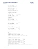
Stat A. Response displays various operating status. Note the response for technical support.
o
Event Mode Value is displayed as:
0
–
SOE
1
–
MOST RECENT
•
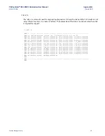
Tally A. Response displays various operating counters. Note the response for technical support.
Table 36: DNP3 Outstation Station Manager
command ‘tally a’
counters
Counters
Description
Psh_Ev02
Displays the number of Point Push Events generated for Digital Inputs
Psh_Ev11
Displays the number of Point Push Events generated for Digital Output
Status
Psh_Ev32
Displays the number of Point Push Events generated for Analog Inputs
Psh_Ev42
Displays the number of Point Push Events generated for Analog Output
Status
Soe_Ev02
Displays the number of SOE Events generated for Digital Inputs
Soe_Ev11
Displays the number of SOE Events generated for Digital Output Status
Soe_Ev22
Displays the number of SOE Events generated for Binary Counters
Soe_Ev32
Displays the number of SOE Events generated for Analog Inputs
Soe_Ev42
Displays the number of SOE Events generated for Analog Output Status
Events02
Displays the number of Events generated for Digital Inputs
Events11
Displays the number of Events generated for Digital Output Status
Events22
Displays the number of Events generated for Binary Counters
Events32
Displays the number of Events generated for Analog Inputs
Events42
Displays the number of Events generated for Analog Output Status
Events43
Displays the number of Events generated Analog Output Values
Cla1_RBE
Displays the number of Events generated for Class1
Cla2_RBE
Displays the number of Events generated for Class2
Cla3_RBE
Displays the number of Events generated for Class3
IIN[x]_Bit
Displays the Internal Indication bits (IIN bits) that are set for the respective
Channel ‘x’. x
-> Channel 1 to Channel 8.
Ob01RdOK Displays the count of Successful Reads from PLC for Digital Inputs
Ob01RdEr
Displays the count of Failed Reads from PLC for Digital Inputs

