PACSystems™ RX3i DNP3 Outstation User Manual
Section 1
GFK-3103B
June 2020
Introduction
9
1.9
DNP3 Outstation Specifications
1.9.1
DNP3 Outstation Objects and Variance support
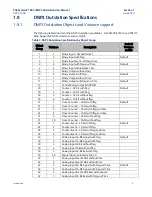
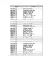
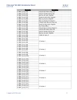
The following tables document the DNP3 Outstation capabilities. For CPE400/CPL410 and CPE115
Refer Appendix B DNP3 Outstation Device Profile.
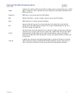
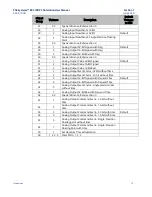
Table 1: DNP3 Outstation Specifications by Object Group
Object
Group
Variance
Description
Default
Variance
in PME
1
1
Binary Input
–
Packed format
1
2
Binary Input with Flag
Default
2
1
Binary Input Event - Without time
2
2
Binary Input with Flag and Time
Default
2
3
Binary Input with Relative Time
10
1
Binary Output without Flag
10
2
Binary Output with Flag
Default
11
1
Binary Output without Time
11
2
Binary Output with Flag and Time
Default
12
1
Control Relay Output Bit (CROB)
20
1
Counter
–
32-bit with flag
Default
20
2
Counter
–
16-bit with flag
20
5
Counter
–
32-bit without flag
20
6
Counter
–
16-bit without flag
21
1
Frozen Counter
–
32-bit with flag
Default
21
2
Frozen Counter
–
16-bit with flag
21
5
Frozen Counter
–
32-bit with flag and time
21
6
Frozen Counter
–
16-bit with flag and time
21
9
Frozen Counter
–
32-bit without flag
21
10
Frozen Counter
–
16-bit without flag
22
1
Counter Event
–
32-bit with flag
Default
22
2
Counter Event
–
16-bit with flag
22
5
Counter Event
–
32-bit with flag and time
22
6
Counter Event
–
16-bit with flag and time
30
1
Analog Input 32-Bit Signed with Flag
Default
30
2
Analog Input 16-Bit Signed with Flag
30
3
Analog Input 32 Bit without flag
30
4
Analog Input 16Bit without flag
30
5
Analog Input 32-Bit Real with Flag
30
44
Special Variance, Refer section 0
32
1
Analog Input Event 32Bit without time
32
2
Analog Input Event 16Bit without time
32
3
Analog Input 32-Bit Signed with Flag and Time
Default
32
4
Analog Input 16-Bit Signed with Flag and Time
32
5
Analog Input Event 32Bit Real without time
32
7
Analog Input 32-Bit Real with Flag and Time

