


7
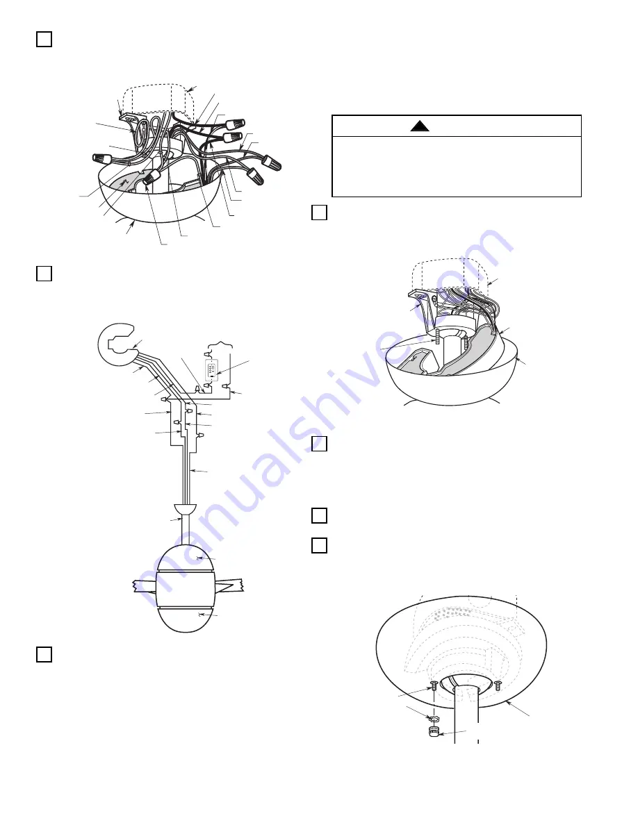
1. Pull the wire leads, coming from the end of the
downrod, and the supply wires through the open
side of the hanger bracket (Figure 9).
2. Position the Emerson SW105 Receiver (supplied)
in the ceiling cover so that the flat side of the
receiver faces up and the open portion of the
receiver is to the right, as shown in Figure 9.
3. Using wire connectors (supplied), make wiring
connections as follows (Figure 9 and 10):
a. Connect the green ground wires from the
hanger bracket and the hanger ball to the supply
ground wire (bare or green).
b. Connect the white fan wire and the white
supply wire to the white receiver wire (AC
IN/MOTOR N).
c. Connect the black fan wire to the black receiver
wire (TO MOTOR L).
OUTLET BOX
BLACK SUPPLY WIRE
BLACK/WHITE RECEIVER
WIRE
BLACK FAN WIRE
BLUE FAN WIRE
BLUE RECEIVER
WIRE
YELLOW FAN WIRE
YELLOW RECEIVER
WIRE
CEILING COVER
WHITE RECEIVER WIRE
WHITE FAN WIRE
WIRE CONNECTOR
SW105
RECEIVER
WHITE SUPPLY
WIRE
SUPPLY
GROUND
WIRE
(GREEN OR
BARE)
HANGER BALL
GROUND WIRE
(GREEN)
HANGER BRACKET
GROUND WIRE
(GREEN)
HANGER BRACKET
BLACK RECEIVER WIRE
OPEN
PORTION OF
RECEIVER
HERE
Figure 9
DOWNROD
WHITE SUPPLY WIRE
BLACK FAN WIRE
SW105 RECEIVER
LISTED GENERAL
USE ON/OFF WALL
SWITCH OR
OPTIONAL
EMERSON SW115
WALL CONTROL
YELLOW RECEIVER WIRE
WHITE FAN WIRE
BLUE RECEIVER WIRE
BLUE FAN WIRE
BLACK
SUPPLY
WIRE
WHITE RECEIVER WIRE
BLACK RECEIVER WIRE
BLACK/WHITE RECEIVER WIRE
LOWER LIGHT FIXTURE
YELLOW FAN WIRE
UPPER LIGHT FIXTURE
TO
110V SUPPLY
EMERSON
®
HI
MED
LOW
FAN OFF
ON
OFF
REV
D/L
U/L
Figure 10
d. Connect the black supply wire to the black/white
receiver wire (AC IN L).
e. Connect the blue fan wire to the blue receiver
wire (BOTTOM LIGHT).
f. Connect the yellow fan wire to the yellow
receiver wire (UPPER LIGHT).
4. After connections have been made, separate the
white and green wires from the black, blue, and
yellow wires.
5. Carefully turn the wires upward and insert them up
through the open side of the hanger bracket and
into the outlet box (Figure 11). Push the green and
white wires into one side of the outlet box; push the
black, blue, and yellow wires into the other side of
the outlet box.
6. Screw the two threaded studs (supplied) into the
tapped holes in the hanger bracket (Figure 11).
7. Slide the receiver up and seat on the hanger
bracket. Then lift the ceiling cover up to the
threaded studs and turn until the studs protrude
through the holes in the ceiling cover (Figure 12).
OUTLET BOX
RECEIVER
CEILING COVER
HANGER BRACKET
1-1/4"
THREADED
STUDS (2)
Figure 11
#8 INTERNAL TOOTH
LOCKWASHERS
1-1/4"
THREADED STUD
CEILING COVER
#8-32 KNURLED KNOB
Figure 12
Check to see that all connections are tight, including
ground, and that no bare wire is visible at the wire
connectors, except for the ground wire. Do not
operate fan until blades are in place. Noise and fan
damage could result.
WARNING
!


