8. Secure the ceiling cover in place by sliding
lockwashers over the threaded studs and installing
the two knurled knobs (supplied) (Figure 12).
Tighten the knurled knobs securely until the ceiling
cover fits snugly against the ceiling and the hole in
the ceiling cover is clear of the downrod. Your fan
is now wired to be turned on and off from the
remote control.
Installing Lower Light
Glass Bowl
1. Screw a 40-watt (maximum) candelabra base bulb
into each of the three light sockets on the lower
light fixture (Figure 13).
2. Place the lower light glass bowl into the lower light
fixture plate, aligning the three flat areas on the top
flange of the glass bowl with the three raised
dimples in the light fixture plate. Then turn the
glass bowl clockwise until it stops (Figure 13).
NOTE: Periodically check that the glass bowl is
seated fully clockwise in the light fixture plate.
Replacing Upper LIght
Fixture Bulbs
NOTE: To prevent damage to the receiver, turn
“off” the electricity at the wall switch before
installing or removing light bulbs on the ceiling fan.
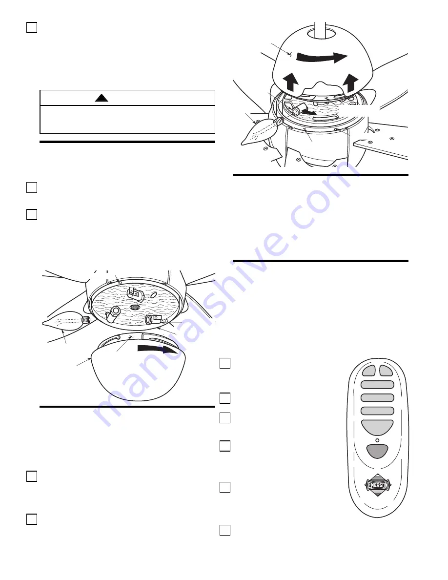
1. Carefully turn the upper glass bowl counter-
clockwise and then raise to expose the lamp
sockets (Figure 14). Grasp the socket of the
defective bulb and rotate the socket outwards, then
remove the bulb.
2. Install a 25-watt candelabra base bulb and rotate
the socket back to its original position. Carefully
lower the glass bowl into the light fixture plate,
aligning the flat areas on the glass flange with
raised dimples on the upper light plate. Turn the
glass bowl clockwise until it stops.
8
To avoid possible fire or shock, make sure that the
electrical wires are completely inside the outlet box and
not pinched between the ceiling cover and the ceiling.
WARNING
!
LOWER LIGHT
FIXTURE PLATE
FLAT AREA
LOWER LIGHT
GLASS BOWL
40-WATT BULB
LIGHT SOCKET
RAISED DIMPLE
Figure 13
UPPER LIGHT
GLASS BOWL
UPPER LIGHT
FIXTURE PLATE
LIGHT
SOCKET
RAISED DIMPLE
FLAT AREA OF THE
GLASS FLANGE
TO LOOSEN
25-WATT
BULB
Figure 14
Installation of
Storage Bracket
A storage bracket is supplied with the remote control
for holding the transmitter when not in use. If you
desire to use the bracket, use the two screw
(supplied) and install it on a wall that is away from
excess heat or humidity.
OPERATION
IMPORTANT
Fan installation must be completed, including the
installation of the fan blades, before testing of the
remote control.
Restore electrical power to the outlet box by turning
the electricity on at the main fuse box. Your remote
control (Figure 15) now has full control of your fan and
lights.
1. To set the desired fan speed,
press the HI, MED, or LOW
button to operate your fan on
high, medium, or low speed.
2. To turn your fan off, press the
OFF button.
3. To change the airflow direction
of the fan blades, press the
REV button.
4. To turn the downlight on,
press and release the DN
button. The light will turn on at
the light intensity previously
selected.
5. To turn the uplight on, press
and release the UP button.
The light will turn on at the
light intensity previously
selected.
6. To vary the intensity of the light, hold the DN or UP
button down until the desired light intensity is
reached, then release the button.
®
OFF
REV
LOW
MED
HIGH
UP
DN
Figure 15


