background image

22      Chapter 3  Installation and Wiring 

EV1000 Series General Purpose Variable Speed Drive    User Manual 

3

CN5 Terminals Wiring 

The layout of CN5 is shown in the figure below: 

TB

TA

TC


TA-TB: normally closed; TA-TC: normally open 

Contact capacity: 250VAC/2A

COS

φ

=1

),

250VAC/1A

COS

φ

=0.4

),

30V

DC

 /1A 

TA, TB and TC can be defined as multi-functional digital output signals. Please refer to Section 5.8. 

If there are inductive loads, such as: electro-magnetic relay and contactor, surge snubber circuit, e.g. RC 
circuit, varistor, fly-wheel diode (pay attention to the polarity when used in a DC circuit), should be 
installed. Note that the leakage current should be less than the current in the contactor or relay. The 
components in the snubber circuit should be installed near to the relay or contactor coil.   

4

CN6 Wiring 

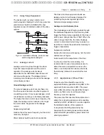
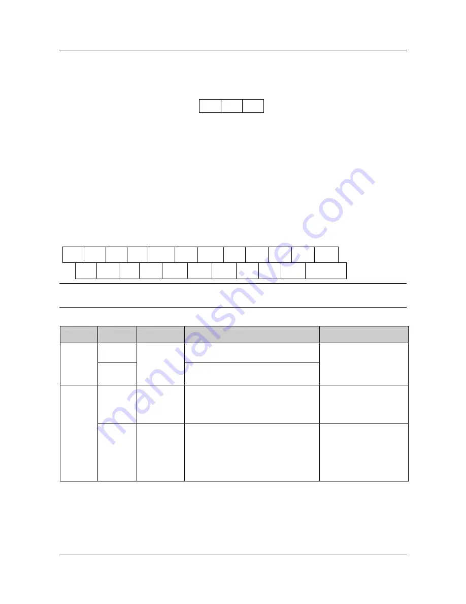
CN6 Terminal strip layout: 

P24 X1  X2  X3 COM  X4  X5 

  VRF

VCI

CCI

GND 

P24 PLC  Y1  Y2  COM FWD

REV

AO1

AO2

GND

+RS485- 


Hint


The “+RS485-” in the above figure means RS485+ and RS485-. 


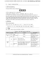
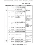
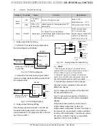
Table 3-8    CN5, CN6 Terminal Function Table 

Category  Terminals 

Name 

Function 

Specification 

RS485+ RS485 

Communic

ation 

RS485- 

RS485 
communication 
port 

RS485 - 

Standard RS-485 
communication port, please 
use twisted-pair cable or 
shielded cable. 

VCI 

Analog input 
VCI 

analog voltage input 

(reference ground: GND) 

Input voltage range:0~10V 

(input resistance:100k

Ω

resolution:1/2000 

Analog 

input 

CCI 

analog input 
CCI 

accept analog voltage/current input. Jumper 
CN10 can select voltage or current input 
mode, Voltage input mode is the 
default.(reference ground: GND) 

Input voltage range:0~10V 
(input resistance:100k

Ω

Input current range:0~20mA 
(input resistance:500

Ω

resolution:1/2000  

艾默生变频器、艾默生CT高级授权代理商--广州盟雄 020-85543394 qq:2294731312

Summary of Contents for EV1000-2S0004G

Page 1: ...e center Copyright 2004 by Emerson Network Power Co Ltd All rights reserved The contents in this document are subject to change without notice Emerson Network Power Co Ltd Address No 1 Kefa Rd Science Industry Park Nanshan District 518057 Shenzhen China Homepage www emersonnetworkpower com cn Customer Service Hotline 800 820 6510 86 21 23017141 86 755 86011668 E mail support emersonnetwork com cn ...

Page 2: ...艾默生变频器 艾默生CT高级授权代理商 广州盟雄 020 85543394 qq 2294731312 ...

Page 3: ...8 Chapter 4 Operation Procedures 29 4 1 Definitions of Terms 29 4 1 1 The Drive s Control Modes 29 4 1 2 Frequency Setting Methods 29 4 1 3 Drive s Operating Status 29 4 1 4 Operating Mode 29 4 2 Operation Guide 30 4 2 1 Operation of LED Keypad 30 4 2 2 Keypad Function Explanation 31 4 2 3 Indicator Description 31 4 2 4 Parameter Setting Method 31 4 2 5 Speed Setting 33 4 2 6 How to Lock Unlock Ke...

Page 4: ...艾默生变频器 艾默生CT高级授权代理商 广州盟雄 020 85543394 qq 2294731312 ...

Page 5: ... control zero frequency hysteresis main and auxiliary frequency setting traverse operation length control etc It is an integral cost effective and highly reliable solution for manufacturer in the related fields EV1000 Series can satisfy the customers requirements on low noise and EMI by using optimized PWM technology and EMC design This manual provides information on installation wiring parameter ...

Page 6: ...he danger of electric shock and explosion For drives that have been stored for longer than 2 years increase its input voltage gradually before supplying full rated input voltage to it in order to avoid electric shock and explosion Perform the maintenance job after confirming that the charging LED is off or the DC Bus voltage is below 36V Only trained professionals can change the components it is p...

Page 7: ...re that the motor can still provide sufficient torque to the load Lubrication of mechanical devices Over time the lubricants in mechanical devices such as gear box geared motor etc when running at low speed will deteriorate Frequent maintenance is recommended Regenerative Energy When lifting load regenerative energy is produced the drive will trip on overvoltage when it cannot absorb the regenerat...

Page 8: ... be used out of the specified range of operation voltage If needed please use suitable voltage regulation device Protection against lightning strike There are transient surge suppressors inside the Drive which protects it against lighting strike Derating due to Altitude Derating must be considered when the drive is installed at high altitude greater than 1000m This is because the cooling effect of...

Page 9: ...ation Speed range 1 50 Starting torque 150 rated torque at 1Hz Accuracy of speed at steady state 1 rated synchronous speed Accuracy of frequency Digital setting highest frequency 0 01 Analog setting highest frequency 0 2 Setting frequency resolution Digital setting 0 01Hz Analog setting highest frequency 0 1 Torque boost Auto torque boost Manual torque boost 0 1 30 0 V F curve 4 modes 1 self defin...

Page 10: ...etting Analog voltage current setup pulse setting serial port Pulse output terminal 0 50kHz pulse signal output Signals can be reference frequency and output frequency Operating function Analog output terminals 2 analog outputs of 0 4 20mA and 0 10V selectable Able to output signals like reference frequency and output frequency LED keypad Able to show 21 parameters such as frequency setting output...

Page 11: ...0 4T0022G 4 0 5 8 5 0 2 2 EV1000 4T0037G EV1000 4T0037P 5 9 10 5 8 8 3 7 EV1000 4T0055G EV1000 4T0055P 8 9 14 6 13 0 5 5 2 2 2 Ordering Information Refer to Fig 2 1a and Fig 2 1b series motor power kW code 0004 0007 0015 0022 0037 0055 0 4 0 75 1 5 2 2 3 7 5 5 4 T 0 0 2 2 G EV1000 input code voltage code 220V 2 380V 4 code type fan pump contant torque P G Fig 2 1a Explanations of Drive Models EV10...

Page 12: ... Keypad Display Unit TDP LED02 Size The LED keypad display unit TDP LED02 standard configuration also applies to TD1000 series drives Through it operation and configuration of the drive can be done Refer to its size in Fig 2 3 Fig 2 3 LED keypad display unit 2 3 Optional Parts You may order the optional parts below from our company 2 3 1 Braking Resistor The drive is equipped with braking unit If ...

Page 13: ...o use terminal control mode after testing and no need to modify the parameters thereafter you may order one TDP LED02 display unit to do the test and for the rest TDP LED03 can satisfy your need as well In this case the frequency setting and operation control are done through terminals You can know the status of the drive through TDP LED03 POW RUN ERR Attention the panel is for status display only...

Page 14: ... setting output voltage and current analog close loop feedback analog close loop setting and external counting value automatically 2 Cable for the Flush Mount Faceplate Model FRC21W1 3 0M FRC21W2 30M For connecting the flush mount faceplate and the drive 3 Profibus Adapter Model TDS PA01 Able to connect EV1000 drive to PROFIBUS network via the TDS PA01 In the PROFIBUS network system the drive oper...

Page 15: ...s The requirements on mounting space and clearance are shown in Fig 3 1 and Fig 3 2 When two Variable Speed Drives are mounted one on top the other an air flow diverting plate should be fixed in between as shown in Fig 3 2 10cm or above 5cm or above 5cm or above 10cm or above air expulsion by fan Fig 3 1 Installation clearances DRIVEⅠ DRIVEⅡ Electric cabinet Fig 3 2 Installation of several drives ...

Page 16: ... 3 Refer to Appendix 3 for the specifications of optional parts Mechanical system manufacturing mechanics Sensor such as temperature position pressure Control Equipment Such as PC Mains Input reactor Linear noise filter Input Filter Drive electric cabinet Area Ⅴ Area Ⅲ Area Ⅰ Area Ⅵ Motor Area Ⅱ earthing separation board Area Ⅳ detecting signal cable Motor cables Fig 3 4 Recommended System Layout ...

Page 17: ...le must be shielded 10kV Power Transformer Motor metal cabinet AC input reactor Metal cabinet PLC or meters circuit breaker filter AC Output reactor 30cm 50cm Drive motor cable control cable 20cm Power source cable of inverter Isolation Transformer power source cable of meters Fig 3 5 Installation of the drive 3 1 2 Noise Suppression The noise generated by the drive may disturb the equipment nearb...

Page 18: ...e power cables they should be placed at right angle to one another 2 Install radio noise filter and linear noise filter ferrite common mode choke at the input and output sides of the drive to suppress the emission noise of power lines 3 Motor cables should be placed in a tube thicker than 2mm or buried in a cement conduit Power cables should be placed inside a metal tube and be grounded by shieldi...

Page 19: ...signed for protecting the product against high order harmonics surge leakage current Leakage current between lines The line leakage current flowing outside through the distributed capacitors of the drive may false trigger the thermal relay especially for the drive of which power rating is less than 7 5kW When the cable is longer than 50m the ratio of leakage current to motor rated current may incr...

Page 20: ...ive to motor are longer than 80m multi strand cables and an AC line reactor should be used to suppress the high frequency harmonics Thus the motor insulation is protected At the same time leakage current and unexpected trigger are reduced 3 2 Wiring Danger Wiring can only be done after the Variable Speed Drive s AC power is disconnected all the LEDs on the operation panel are off and after waiting...

Page 21: ...3 2 1 Overview You should finish the power circuit and control circuit wiring First remove the screws on the keypad open the front door and then you will see the power terminals and control terminals For different models of the drive the power terminals layout is different which will be described in details later Beneath the keypad display unit there are control terminal strip CN5 CN6 and jumper C...

Page 22: ...CN10 0 2 10V CN16 0 4 20mA Multifuction input 2 Multifuction input 3 Multifuction input 4 Multifuction input 5 CN17 0 2 10V 0 4 20mA Y2 P Power circuit Control circuit P24 Fig 3 7 Systematic Wiring Diagram Hint 1 In the above Figure O is the terminal in power circuit and is the control terminal 2 Terminal CCI can input voltage or current signal by switching the jumper CN10 on control board 3 Built...

Page 23: ... circuit uses multi strand cable the single core cable section area can be 0 5mm2 3 2 2 Power Terminals 1 EV1000 2S0004G EV1000 2S0007G The power terminal layout is shown in the figure below P PB U W V N L Table 3 3 Definitions of Power Terminals Mark Definition L N 1 phase AC 220V input P PB External braking resistor P DC positive negative bus input U V W 3 phase AC outputs PE Protective earth on...

Page 24: ...on in Table 3 7 Be sure to set the jumper and wire the terminals properly It is recommended to use cable of section area bigger than 1mm2 CN16 CN17 CN10 CN6 CN5 CN3 Fig 3 8 Layout of Control Terminals and Jumpers Table 3 6 Function of Control Terminals Mark Function CN5 Relay outputs CN6 Analog I O digtial I O Table 3 7 Jumpers Function Mark Function Setting Default CN10 CCI current voltage input ...

Page 25: ...Chapter 3 Installation and Wiring 21 EV1000 Series General Purpose Variable Speed Drive User Manual 艾默生变频器 艾默生CT高级授权代理商 广州盟雄 020 85543394 qq 2294731312 ...

Page 26: ...stalled near to the relay or contactor coil 4 CN6 Wiring CN6 Terminal strip layout P24 X1 X2 X3 COM X4 X5 VRF VCI CCI GND P24 PLC Y1 Y2 COM FWD REV AO1 AO2 GND RS485 Hint The RS485 in the above figure means RS485 and RS485 Table 3 8 CN5 CN6 Terminal Function Table Category Terminals Name Function Specification RS485 RS485 Communic ation RS485 RS485 communication port RS485 Standard RS 485 communic...

Page 27: ...aving the same function as X1 X3 besides it can be defined as high speed pulse inputs see Section 5 8 Reference ground COM Optical isolator 2 way input Single way max input frequency 100kHz 2 way max input frequency 50kHz Max reference pulse frequency 50Hz Input voltage range 9 30V Input impedance 620Ω FWD Run forward command Optical isolator two way input programmable terminal max input frequency...

Page 28: ... Output Terminal Wiring If the analog output terminal AO1 and AO2 are connected with analog meter it can measure many parameters The jumpers for AO1 and AO2 are CN16 and CN17 analog current output AO1 CN16 AO2 CN17 AO1 AO2 GND 0 4 20mA 0 2 10V analog meter anlog voltage output 0 4 20mA 0 2 10V PV Series Fig 3 11 Analog Output Terminal Wiring Hint 1 When using analog input you should install capaci...

Page 29: ...be connected together z RS485 communication uses shielded cables which is earthed at one side The earth wire of the shielded cable is connected to RS485 communication module PE If the above standard wiring methods cannot meet the requirements you can take the actions below z Use isolated RS485 communication module z If the noise is transmitted through the GND line to the drive or other devices whi...

Page 30: ...n emitters are connected as shown in Fig 3 16 shield grounded near the drive EV1000 PE PLC FWD P24 COM 24V DC D2 3 3V X5 3 3V External controller Fig 3 16 Internal 24V Wiring Diagram drain When using External power supply remember to disconnect PLC and P24 9 30V shield earthed near the drive EV1000 PE PLC FWD P24 COM 24V DC D2 3 3V X5 3 3V External controller Fig 3 17 External Power Supply Wiring ...

Page 31: ...les relay cables and cables of contactor The cables should be vertical to each other to reduce the disturbance to minimum 3 2 4 Onsite Wiring Requirements To avoid mutual EMI disturbance the control cables power cable and motor cable should be installed as apart as possible especially when they are routed in parallel for rather long distance If the signal cable must cross the power cable or motor ...

Page 32: ...tor cable the end of one cable should be connected to the PE of the drive and the other end should be connected to the motor s enclosure If the motor and the drive each has its own earthing pole then the earthing effect is better If the earthing poles of different equipment in one system are connected together then the leakage current will be a noise source that may disturb the whole system Theref...

Page 33: ... How to set Frequency The output frequency is decided after calculating the values from one or more of the 7 frequency setting channels which involves the concept of main and auxiliary reference frequency Main reference frequency set by F0 00 multi speed MS or close loop control The main reference frequency is decided by the priority of running mode The priority level is Jog close loop PLC MS mult...

Page 34: ... function group It can be disabled by multi function terminal function No 21 MS Running Select multi frequency 1 7 F3 23 F3 29 by the combination of multi function terminal function No 1 2 3 which is not zero Simple Running open loop operation The above 5 operating modes determine 5 frequency setting sources Except Jog the other four frequency setting can be adjusted or combined with auxiliary fre...

Page 35: ...entiometer Set frequency 4 2 3 Indicator Description Function of the Indicators on the keypad Indicator Meaning Color Mark Frequency indicator ON current LED display is frequency Green Hz Current indicator ON current LEDdisplay is current Green A Voltage indicator ON current LEDdisplay is voltage Green V Potentiometer indicator Set frequency by the potentiometer Green None Status indicator ON the ...

Page 36: ...tate the LED displays F0 2 Press FUNC DATA key F0 00 is displayed Press key until F0 12 is displayed 3 Press FUNC DATA key you will see 50 00 4 Press key to move the cursor to the digit 5 5 Press key once to change the digit to 4 6 Press FUNC DATA key to save the modification and you will see the next parameter F0 13 7 Press PRG key to exit the programming state enter menu level 3 F0 12 enter menu...

Page 37: ...before compensation BIT1 output freq after comensation BIT2 set freq BIT3 output current A BIT0 actual speed rpm BIT1 set speed rpm BIT2 actual line speed m s BIT3 set line speed m s BIT0 output power BIT1 output torque BIT2 reserved BIT3 reserved BIT0 reserved BIT1 reserved BIT2 reserved BIT3 reserved Under menu level 3 if no digit of a parameter is blinking it means it is unchangeable The possib...

Page 38: ... Lock LED Keypad Display Unit Unlock at stop or operating state press FUNC DATA key and then press three times Note that the operation will not change the value of F9 07 Note Even though the hundred s place of F9 07 is not zero allow to lock the keypad every time the drive is powered up the keypad is not locked F0 F9 50 00 F9 00 F9 07 0020 0020 0120 F9 08 F9 50 00 50 00 FUNC DATA FUNC DATA FUNC DA...

Page 39: ...X5 see F7 03 F7 04 The input pulse range 15 30V 0 50 0kHz 6 Keypad Analog Setting The reference frequency is set by the potentiometer on the keypad Range 0 max output frequency F0 05 Note For method 3 4 and 5 the frequency calculation curve is given in F1 00 F1 11 please refer to 5 2 F0 01 Digital Frequency Control Range 00 11 00 Valid only when F0 00 0 1 2 Thousand Hundred Ten One 0 Save after po...

Page 40: ... frequency of the motor It is the Min frequency when the drive outputs the highest voltage as shown in Fig 5 2 as fb Max output voltage is the drive s output voltage when the drive outputs base frequency as shown in Fig 5 2 as Vmax This corresponds to the rated voltage of the motor fmax output voltage fb fH fL output frequency Vmax Fig 5 2 Characteristic Parameters Definition The fH and fL are def...

Page 41: ...per limet max output frequency 50 00Hz F0 13 Lower limit of frequency Range 0 upper limet of frequency 0 00Hz Please refer fH and fL in Fig 5 2 Note It is possible for the actual output frequency to fluctuate within 2 5Hz in the bus voltage control process F0 14 V F curve setting Range 0 3 0 F0 15 V F freq F3 Range F0 17 F0 06 0 00Hz F0 16 V F voltage V3 Range F0 18 100 0 0 0 F0 17 V F freq F2 Ran...

Page 42: ... of reference frequency selector Range 0 00 9 99 1 00 F1 02 Filter constant Range 0 01 50 00s 0 50s F1 03 Max input pulse freq Range 0 1 50 0kHz 10 0kHz F1 04 Ratio of Min input of curve 1 to F1 03 Range 0 0 100 0 0 0 F1 05 Frequency corresponds to min input if curve 1 Range 0 0 650 0Hz 0 00Hz F1 06 Ratio of Max input of curve 1 to F1 03 Range 0 0 100 0 100 0 F1 07 Frequency corresponds to max inp...

Page 43: ...on 0 Curve1 1 Curve2 Pulse curve selection 0 Curve 1 1 Curve 2 Fig 5 9 Frequency Curve Selection Suppose you want to set reference frequency by terminal pulse signal input signal range 1kHz 20kHz 1kHz input for reference frequency 50Hz 20kHz input for reference frequency 5Hz To meet the above requirement you should set F0 00 5 set terminal pulse mode F7 03 45 input pulse signal from X4 F1 00 100 s...

Page 44: ... brake time at startup Range depending on model 0 0s F2 03 and F2 04 are valid only when you set F2 00 1 that is braking before starting See Fig 5 12 DC brake current at startup is determined by drive model for G type 0 150 of drive s rated current max current among the 3 phases P type 0 130 of drive s rated current max current among the 3 phases If the brake time at startup is set at 0 0s no brak...

Page 45: ... deceleration time 1 Coast to stop When the drive receives Stop command it will stop outputting frequency and stop gradually relying on load inertia 2 Deceleration DC braking When the drive receives Stop command it will reduce output frequency within preset Dec time When it arrives at the frequency threshold of DC braking the DC braking begins Please refer to F2 09 F2 12 F2 09 Frequency threshold ...

Page 46: ...minal and serial port F3 01 FWD REV transition time Range 0 3600s 0 0s It refers to the time period when the drive s rotation changes from FWD to REV or REV to FWD see Fig 5 16 as t1 Time t1 Output frequency Fig 5 16 Transition time from FWD to REV F3 02 F3 04 RESERVED F3 05 Auto energy saving Range 0 1 0 0 disabled 1 enabled The drive can detect load current and adjust voltage accordingly to save...

Page 47: ...ated slip must be set correctly FH 08 F3 10 Carrier wave frequency CWF Range 0 7 15 0kHz Depending on model Table 5 1 Relation of Model and Carrier Freq CWF Model Default kHz EV1000 2S0007G 8 Others 10 Table 5 2 Carrier Freq and Performance CWF Performance Decreasing Increasing Motor noise Leakage current Interference Note 1 To get the best control effect the ratio of carrier wave frequency to the...

Page 48: ...s min 6 0s F3 22 Dec time 4 Range 0 1 3600s min 6 0s Three kinds of Acc Dec time can be defined and the drive s Acc Dec time 1 4 can be selected by different combinations of control terminals refer to F7 00 F7 07 for the definitions of terminals used to select Acc Dec time Note Acc time 1 and Dec time 1 is defined in F0 10 and F0 11 respectively F3 23 MS Freq 1 Range Lower limit upper limit 5 00Hz...

Page 49: ...0mS signals from output terminals Y1 and Y2 of open collector output or relay output See F7 10 F7 12 F4 00 Simple PLC mode Range 0000 1123 0000 Thous Hund Ten One PLC running mode selection 0 disabled 1 stop after single cycle 2 retain value after 1 cycle 3 continuous Save PLC status after poweroff 0 not save 1 save the stage and frequency at poweroff PLCrunning after interrupt 0 start from first ...

Page 50: ...cc time of stage 1 2 Acc time of stage 2 a3 Acc time of stage 3 2 Dec time of stage 2 f 1 Freq of stage 1 2 Freq of stage 2 f 3 Freq of stage 3 Operating time of stage 2 Time a d f Fig 5 25 PLC Restart Mode 1 2 Start from the frequency where it stops When the drive stops caused by Stop command or fault it can record both the time it has undergone in the current stage and the very frequency when th...

Page 51: ... and F4 13 are to set frequency direction Acc Dec time of PLC stages See Fig 5 27 T H Ten One Frequency setting 0 Preset frequency i 1 Determined by F0 00 2 Preset close loop reference i 3 Determined by F5 01 Acc Dec time selection 0 Acc Dec 1 1 Acc Dec 2 2 Acc Dec 3 3 Acc Dec 4 Running direction selection 0 Forward 1 Reverse 2 Determined by running command Reserved Fig 5 27 PLC Stage i setting i ...

Page 52: ...suring generator as speed close speed loop control PG speed close loop control A speed close loop control system can be formed by external control terminals X4 and X5 and pulse generator PG As shown in Fig 5 29 close speed loop input can come from a potentiometer in the form of voltage signal via terminal VCI while the feedback value of the close loop is input by PG in pulse mode via terminal X4 a...

Page 53: ...ough F5 16 to satisfy different applications In order to meet the control requirements the motor s speed should be increased with reference speed This kind of control characteristic is called positive response If the motor speed is required to be decreased when the reference value is increased this control characteristic is called negative response See Fig 5 32 F5 16 defines the two characteristic...

Page 54: ... Range 0 01 50 00s 0 50s F5 04 Feedback filter Range 0 01 50 00s 0 50s Both the input signal and feedback signal have some noise signals These signals can be filtered by setting the time constant of filter settings of F5 03 and F5 04 The bigger the time constant the better the immunity capability but the response becomes slow The smaller the time constant the faster the response but the immunity c...

Page 55: ...ulator stops operation when the feedback error is within this range Setting this parameter correctly is helpful to improve the system output accuracy and stability Error limit Feedback value Ref Output Freq time time Fig 5 34 Error Limit Schematic Diagram F5 16 Close loop regulation characteristic Range 0 1 0 0 Positive logic Set F5 16 to 0 if the motor speed is required to increase with the refer...

Page 56: ... be used MS close loop setting 1 7 can be selected through external terminals please refer to F7 00 F7 04 function No 30 32 It can also used with simple PLC close loop see F4 parameters The MS close loop setting has priority over the methods defined in F5 01 5 7 Traverse Parameters F6 Traverse function applies to textile and chemical fiber industry or others that requires lateral movement or rolli...

Page 57: ...ing at the PLC preset frequency within Acc Dec time When receiving Stop command the drive will stop according to PLC Dec time F6 00 Traverse function selection Range 0 1 0 0 disabled 1 enabled F6 01 Traverse mode Range 0000 1111 0000 This parameter is to set the operating mode of traverse Refer to the figure below Thou Ten One Start mode 0 auto 1 terminal config manually Restart mode 0 start to th...

Page 58: ...set at manually start Please refer to Fig 5 36 F6 04 Traverse amplitude Range 0 0 50 0 0 0 Varied amplitude AW central frequency F6 04 Fixed amplitude AW max frequency F0 05 F6 04 Note The traverse frequency is limited by upper and lower limit of frequency Improper setting of the frequency limit will result in faults F6 05 Step freq Range 0 0 50 0 of amplitude 0 0 Refer to Fig 5 36 If it is set at...

Page 59: ... Frequency setting method 2 24 Frequency setting method 3 25 Reference freq is input via terminal CCI 26 Reserved Setting Functions 27 Terminal control mode is forcibly enabled 28 Control mode 1 29 Control mode 2 30 MS close loop mode 1 31 MS close loop mode 2 32 MS close loop mode 3 33 Start traverse operation 34 Reset the traverse operating status 35 External stop command 36 Reserved 37 Drive op...

Page 60: ...minal 1 Acc Dec time selection OFF OFF Acc time 1 Dec time 1 OFF ON Acc time 2 Dec time 2 ON OFF Acc time 3 Dec time 3 ON ON Acc time 4 Dec time 4 By combination of the ON OFF state of Terminal 1 and 2 you can get 4 groups of Acc Dec time 6 7 External fault signal normally open close input If the setting is 6 7 fault signal of external equipment can be input via the terminal which is convenient fo...

Page 61: ...pen contacts and X5 normally closed contact Note Different from function 6 7 the external interrupt signal will not cause alarm and the drive will resume previous running once the signal removed 19 DC Braking DB If the setting is 19 the terminal can be used to perform DC injection braking to the motor that is running for emergency stop and accurate location Initial braking frequency braking delay ...

Page 62: ... of X1 X5 Table 5 8 MS Close loop Setting Selection X3 X2 X1 MS close loop reference OFF OFF OFF By F5 01 OFF OFF ON MS Close loop setting 1 OFF ON OFF MS Close loop setting 2 OF ON ON MS Close loop setting 3 ON OFF OFF MS Close loop setting 4 ON OFF ON MS Close loop setting 5 ON ON OFF MS Close loop setting 6 ON ON ON MS Close loop setting 7 The various MS close loop setting is realized by the co...

Page 63: ...signal that is used as frequency reference Refer tp F1 parameters for the relationship between input pulse frequency and the reference frequency 46 Single phase speed measuring input This function is effective only to multi function input terminals X4 and X5 See section 3 2 3 for input characteristics The speed control accuracy is 0 1 Single phase speed feedback control can be realized by using th...

Page 64: ...e frequency F7 10 Open collector output terminal Y1 Range 0 19 0 F7 11 Open collector output terminal Y2 Range 0 32 1 F7 12 Relay output function Range 0 19 16 Refer to section 3 3 2 for the output characteristics of Y1 Y2 and the relay s output terminal Table 5 9 shows the functions of the above 3 terminals Note that one function can be selected repeatedly F7 11 20 32 Y2 is the output pulse frequ...

Page 65: ...ig 5 73 5 Low voltage lock up signal LU The signal will be given when the DC bus voltage is lower than the low voltage limit and the LED displays P oFF 6 External stopping command EXT The terminal outputs the indicating signal if the drive outputs tripping signal caused by external fault E015 7 Higher limit of frequency FHL The signal is given if the preset frequency is higher than upper limit of ...

Page 66: ...ing time Fn 01 reaches preset operating time Fn 00 Note When F7 04 is set at 44 46 the pulse output function of Y2 is disabled automatically F7 13 Freq arrival detection range FAR Range 0 00 650 00Hz 2 50Hz As shown in Fig 5 46 if the drive s output frequency is within the detecting range of preset frequency a pulse signal will be output It is complementary to No 1 function in Table 9 1 detecting ...

Page 67: ...ort directly If F7 26 or F7 27 is set at 11 the output of AO1 or AO2 65535 corresponds to max analog output 10V 20mA Please refer to Appendix 2 Suppose you want AO1 outputs 4 20mA which means the bus voltage is 0 800V You should do the following configuration F7 26 7 output signal presenting bus voltage F7 29 01 AO1 output 4 20mA F7 30 100 output gain 100 Select 0 4 20mA of CN16 jumper F7 29 Analo...

Page 68: ... Thou Hun Ten One s place BIT0 positive negative logic of X1 BIT1 positive negative logic of X2 BIT2 positive negative logic of X3 BIT3 positive negative logic of X4 BIT0 positive negative logic of X5 BIT1 BIT2 BIT3 BIT0 positive negative logic of FWD BIT1 positive negative logic of REV BIT2 positive negative logic of Y1 BIT3 positive negative logic of Y2 BIT0 reserved BIT1 reserved BIT2 reserved ...

Page 69: ...req after comensation BIT2 set freq BIT3 output current A BIT0 actual speed rpm BIT1 set speed rpm BIT2 actual line speed m s BIT3 set line speed m s BIT0 output power BIT1 output torque BIT2 reserved BIT3 reserved BIT0 reserved BIT1 reserved BIT2 reserved BIT3 reserved Fig 5 51 LED Displayed Parameter 1 Setting F8 01 and F8 02 define the parameters that can be displayed by LED when the drive is o...

Page 70: ...ounting value BIT2 actual speed rpm BIT3 prest speed rpm BIT0 actual line speed BIT1 preset line speed BIT2 VCI V BIT3 CCI V BIT0 analog close loop feedback BIT1 analog close loop setting BIT2 actual length BIT3 preset length BIT0 terminal state BIT1 bus voltage BIT2 accumulated length BIT3 reserved Fig 5 54 Parameter Displayed at Stop State F8 01 and F8 02 define the parameters that can be displa...

Page 71: ...y setting method simultaneously Method 1 Change F0 03 Method 2 use terminal X1 X5 function No 28 and 29 For example In order to realize remote and local control it requires that Control modes selection The control modes can be selected by terminal remotely or by F0 03 locally If keypad panel control mode is used press RUN to run the drive and press STOP to stop the drive The preset frequency can b...

Page 72: ...og setting F9 01 4 13 main freq common operation freq F0 00 0 5 MS freq F3 23 F3 29 simple PLC freq F4 00 F4 14 close loop freq F5 00 F5 26 Fig 5 58 Preset Freq Calculation Method Serial port UPDN CCI PULSE VCI Analog Digital Aux ref freq Gain processing F9 02 Pre processing Initial value and sign of aux ref F9 03 and F9 04 Setting F9 04 Setting of F1 00 Setting of F9 01 Pre processing Fig 5 59 Au...

Page 73: ...itial setting of any of the 3 method F9 04 digital auxiliary reference control It is valid when F9 01 1 3 See Fig 5 62 Thou Ten One Save 0 Save ref Freq upon power outage 1 Not save ref Freq upon power outage Stopping freq 0 Hold ref Freq at stop 1 Clear ref Freq at stop Sign of auxi ref Freq 0 main ref auxi ref Freq 1 main ref auxi ref Freq Reserved Hun Fig 5 62 Digital Auxiliary Freq Setting One...

Page 74: ...pecified manner 2 effective for keypad terminal and serial port control In keypad control mode press this key and the drive will stop in specified manner But in terminal or serial port control mode pressing this key will trigger E015 alarm and the drive will coast to stop STOP RESET can be used to reset a fault in all control mode Ten s place reserved Hundred s place lock up keypad selection You c...

Page 75: ... frequency hysteresis control Take analog CCI for example see Fig 5 66 Startup process When the Run command is given out only after CCI current arrives at Ib and the corresponding frequency reaches fb does the drive start and accelerate to the preset frequency Stop During operation if CCI current reduces to Ib the drive will not stop until it reaches Ia and the corresponding frequency becomes fa w...

Page 76: ... if F9 14 is set to 0 but the calculated length is still effective Application of stop at fixed length Fig 5 67 Application of Stop at Fixed Length In Fig 5 67 the drive drives the motor and the motor in turn drives the spindle through the conveyer The shaft that contact with the spindle can measure the line speed of it which will be transmit to the drive by the sensor in the form of pulse The dri...

Page 77: ...d the drive will not start 4 When restart is allowed the drive will start according to F2 00 5 11 Reserved FA FA 00 FA 11 Reserved 5 12 Communication FF FF 00 Communication config Range 0000 1127H 0005 Thou Hun Ten One Baud rate 0 300bps 1 600bps 2 1200bps 3 2400bps 4 4800bps 5 9600bps 6 19200bps 7 38400bps Data format 0 1 8 1 format no parity 1 1 8 1 format even parity 2 1 8 1format odd parity Vi...

Page 78: ... cannot be ensured FH 03 Current without load I0 Range 0 1 999 9A Depending on model FH 04 Stator resistance R1 Range 0 0 50 00 Depending on model FH 05 Leakage inductance Xl Range 0 0 50 00 Depending on model FH 06 Rotor resistance R2 Range 0 0 50 00 Depending on model FH 07 Mutual inductance Xm Range 0 0 2000 0 Depending on model Please refer the above parameters to Fig 5 69 R m X m I 0 I 1 U 1 ...

Page 79: ...and the stator s resistance R1 rotor s resistance R2 and the leakage inductance X1 will be measured and then the motor begins to rotate mutual inductance XM I0 will be measured and written into FH 04 FH 05 FH 06 FH 07 and FH 03 automatically After auto tuning FH 09 will be set to 0 automatically Auto tuning procedures 1 Set the F0 06 basic operating frequency and F0 07 Max output voltage correctly...

Page 80: ...fferent kinds of motors the Max output current of the drive should be adjusted as shown in Fig 5 70 Motor overload protective coefficient 100 80 1min Time Current 200 160 Fig 5 70 Motor s overload protection coefficient The efficient is calculated by the formula below Motor overload protection coefficient motor rated current inverter s rated output current 100 Generally the Max load current is the...

Page 81: ...nt speed Overload action mode 0 No alarm continue operation 1 Alarm and stop operation Reference current 0 motor s rated current E014 1 drive s rated current E013 Reserved Fig 5 72 Overload Detection Configuration One s place of FL 04 overload detection mode 0 the detection is done as long as the drive is operating 1 the detection is done only when the drive works at constant speed Ten s place of ...

Page 82: ...rotection The action mode of auto current limiting function is decided by FL 09 FL 09 0 disabled FL 09 1 auto current limiting is effective during acceleration or deceleration but ineffective at constant speed no silencing function FL 09 2 effective all the time no silencing function FL 09 3 auto current limiting is effective during acceleration or deceleration but ineffective at constant speed wi...

Page 83: ...0 FL 15 Fault type of the second time Range 0 24 0 FL 16 Fault type of the third time latest Range 0 24 0 FL 17 Bus voltage at the last fault Range 0 999V 0V FL 18 Output current at the last fault Range 0 999 9A 0 0A FL 19 Freq at the last fault Range 0 00 650 00Hz 0 00Hz EV1000 has 24 kinds of alarms It can memorize the types of 3 latest faults FL 14 FL 16 and the voltage current and frequency FL...

Page 84: ...anged 1 No parameters can be changed except the F0 02 and FP 01 2 No parameters can be changed except FP 01 Note The factory setting of FP 01 is 1 If you need modify parameters FP 01 must be set to 0 and then set it to 1 or 2 after modification to protect these parameters FP 02 Parameter initialization Range 0 2 0 0 disabled 1 clear fault record Clear the contents of FL 14 FL 19 2 restore to facto...

Page 85: ...upply E001 Over current in Acc process Drive power is too small Select a higher power drive Too short Dec time Prolong the Dec time Negative torque load or the load inertia is too high Connect suitable braking device E002 Over current in Dec process Too low drive s power Select the drive with larger capacity Sudden change of load Reduce the change of the load Too short Acc Dec time Prolong Acc Dec...

Page 86: ...ure Obstruction of ventilation channel Clear the ventilation channel Fan does not work Replace the fan E011 Rectifier s heatsink overheat Inverter fault Seek service E012 Reserved Reserved Reserved Too short Acc time Prolong Acc time Too large DC braking energy Reduce DC braking current prolong braking time Improper V F curve Adjust V F curve or torque boost value The drive is re started with a ro...

Page 87: ...ectly Serial port communication error Press STOP RESET to reset Seek service Host PC does not work Check whether the host PC is working or not Check the wiring E017 RS232 RS485 communication failure Improper setting of alarm conditions Modify FF 02 FF 0 FL 12 E018 Reserved Reserved Reserved Wires or connectors of control board are loose Check and re wire Auxiliary power supply is damaged Seek serv...

Page 88: ...rs can be changed in stop status Set FP 01 to 1 or 2 Set FP 01 to 0 Settings of part of parameters cannot be changed Parameter s modification property is The parameters cannot be changed by user Input correct user s password Parameter setting cannot be changed No parameter but 0 0 0 0 is displayed when pressing MENU ESC User s password is required Seek service Coast to stop terminal effective Chec...

Page 89: ...ed Check F7 35 Auto reset of fault Check reason of fault and the auto reset function Simple PLC pause Check PLC pause function terminal Interrupt signal feedback from external devices Check the configuration of external interrupt and faulty external devices Stop at zero frequency Check F9 12 and F9 13 Reference frequency is 0 Check the reference frequency Skip frequency Check skip frequency Positi...

Page 90: ...rding to the table below A good way to prolong the lifetime of the drive is to record the routine operation data find out and clear faults in the early stage Table 7 1 Daily Checking Items Object Item Method Criterion Temperature humidity Thermometer hygrometer 10 40 Derate if at 40 50 Dust water and leakage observe No sign of leakage Vibration Vibration meter Less than 5 9m s 2 0 6g Environment G...

Page 91: ...dielectric test again in order to avoid potential damage of its internal components 7 3 Replacing of Easily worn Parts The easily worn parts of the drive are cooling fan and electrolytic capacitor whose life has close relation with the environment and maintenance Refer to the table below Part Life Fan 30 40 thousand hours Electrolytic capacitor 40 50 thousand hours Relay TA TB TC About 100 000 tim...

Page 92: ...e the responsibility of 18 months defects liability period for any faults or damages under the normal operation conditions as of manufacture date After 18 months maintenance will be charged 3 Even within 18 months maintenance would be charged under the following conditions Damages incurred to the drive due to mis operations which are not in compliance with User Manual Damages incurred to the drive...

Page 93: ...s the parameters that are set by factory and the user cannot modify it The drive has already set the auto checking function to the modification property of each parameter so as to avoid wrong modification by the user The drive provides passwords to protect the parameters against unauthorized modifications After the user s password is set that is the settings of FP 00 are not zero the drive will re...

Page 94: ...ntrol One s place of F0 01 0 reference frequency saved upon power failure 1 reference frequency saved upon power failure Ten s place of F0 01 0 reference frequency saved when the drive stops 1 The reference frequency will restore back to F0 02 when the drive stops 1 00 F0 02 Frequency digital setting F0 13 F0 12 when F0 00 0 1 2 0 01Hz 50 00Hz F0 03 Control mode 0 LED keypad control 1 terminal con...

Page 95: ... 50 00Hz F0 13 Lower limit of freq 0 00 F0 12 0 01Hz 0 00Hz F0 14 V F curve 0 user defined V F curve based on F0 15 F0 20 1 curve1 a 2 order curve 2 curve 2 a 1 7 order curve 3 curve 3 a 1 2 order curve 1 0 F0 15 V F freq F3 F0 17 F0 06 0 01Hz 0 00Hz F0 16 V F voltage V3 F0 18 100 0 0 1 0 0 F0 17 V F freq F2 F0 19 F0 15 0 01Hz 0 00Hz F0 18 V F voltage V2 F0 20 F0 16 0 1 0 0 F0 19 V Ffreq F1 0 00 F...

Page 96: ...1 00 PULSE curve selection 0 curve 1 1 curve 2 1 000 F1 01 Gain of reference frequency selector 0 00 9 99 0 01 1 00 F1 02 Filter time 0 01 50 00s 0 01s 0 50s F1 03 Max input pulse freq 0 1 50 0k 0 1k 10 0k F1 04 Ratio of Min input of curve 1 to F1 03 0 0 F1 06 0 1 0 0 F1 05 Frequency corresponds to min input of curve 1 0 00 F0 05 1 0 00Hz F1 06 Ratio of Max input of curve 1 to F1 03 F1 04 100 0 0 ...

Page 97: ...sponds to max input of curve 2 0 00 F0 05 1 50 00Hz Note All the analog value in the table is shown in volt it can be converted to current by the formula V mA 2 Group 2 Start Brake Parameters Para Name Range Unit Default Modification F2 00 Start mode 0 start at start frequency F2 01 1 brake first and then start at start frequency Note start course can refer to the start after first power on power ...

Page 98: ... 0 1 0 0 F2 04 DC brake time at startup 0 0 disabled 0 1 60 0s 0 1s 0 0s F2 05 Acc Dec mode 0 linear 1 S curve 2 auto 1 0 F2 06 S curve start time 10 0 50 0 Acc Dec time F2 06 F2 07 90 0 1 20 0 F2 07 S curve rising time 10 0 80 0 Acc Dec time F2 06 F2 07 90 0 1 60 0 F2 08 Stop mode 0 decelerate to stop 1 coast to stop 2 decelerate to stop DC brake 1 0 F2 09 Frequency threshold of DC braking 0 00 6...

Page 99: ...ynamic braking 0 disabled 1 enabled 1 0 F2 14 Ration of braking time to total operating time 0 0 100 0 0 1 2 0 Group 3 Auxiliary Operating Parameters Para Name Range Unit Default Modification F3 00 Anti reverse setting 0 reverse allowed 1 reverse not allowed 1 0 F3 01 FWD REV transition time 0 3600s 0 1s 0 0s F3 02 Reserved 0 F3 03 Reserved 0 F3 04 Reserved 0 F3 05 Auto energy saving 0 disabled 1 ...

Page 100: ...kHz F3 11 CWF auto adjustment 0 Disabled 1 Enabled 1 1 F3 12 Motor tone 0 10 1 0 F3 13 Jog frequency 0 10 50 00Hz 0 01Hz 5 00Hz F3 14 Jog interval 0 0 100 0s 0 1s 0 0s F3 15 Jog Acc time F3 16 Jog Dec time 0 1 60 0s 0 1 6 0s F3 17 Acc time 2 F3 18 Dec time 2 F3 19 Acc time 3 F3 20 Dec time 3 F3 21 Acc time 4 F3 22 Dec time 4 0 1 3600 default unit S refer to F9 09 0 1 6 0s F3 23 MS freq 1 5 00Hz F3...

Page 101: ...8 MS freq 6 45 00Hz F3 29 MS freq 7 F0 13 F0 12 0 01Hz 50 00Hz F3 30 Skip freq 1 0 00 650 0Hz 0 01Hz 0 00Hz F3 31 Skip freq 1 range 0 00 30 00Hz 0 01Hz 0 00Hz F3 32 Skip freq 2 0 00 650 0Hz 0 01Hz 0 00Hz F3 33 Skip freq 2 range 0 00 30 00Hz 0 01Hz 0 00Hz F3 34 Skip freq 3 0 00 650 0Hz 0 01Hz 0 00Hz F3 35 Skip freq 3 range 0 00 30 00Hz 0 01Hz 0 00Hz 艾默生变频器 艾默生CT高级授权代理商 广州盟雄 020 85543394 qq 22947313...

Page 102: ...ingle cycle 2 Maintain value of the last stage after 1 cycle 3 continuous cycle Ten s place of F4 00 Restart mode after PLC interruption 0 start from the first stage 1 continue from the stage frequency where the drive stops 2 Start from the frequency where it stops Hundred s place of F4 00 Save PLC state after poweroff 0 not save 1 save Thousand s place Selection of time unit 0 Second 1 Minute 1 0...

Page 103: ...of F4 01 0 select MS frequency 1 F3 23 1 decided by F0 00 2 MS close loop setting 1 F5 20 3 decided by F5 01 Ten s place of F4 01 running direction 0 forward 1 reverse 2 depends on Run command Hundred s place of F4 01 Acc Dec time selection 0 Acc Dec time 1 1 Acc Dec 2 2 Acc Dec 3 3 Acc Dec 4 1 000 F4 02 Stage 1 run time 0 0 6500 0 1 20 0 艾默生变频器 艾默生CT高级授权代理商 广州盟雄 020 85543394 qq 2294731312 ...

Page 104: ...of F4 03 0 select MS frequency 2 F3 24 1 decided by F0 00 2 MS close loop setting 2 F5 21 3 decided by F5 01 Ten s place of F4 03 running direction 0 forward 1 reverse 2 depends on Run command Hundred s place of F4 03 Acc Dec time selection 0 Acc Dec time 1 1 Acc Dec 2 2 Acc Dec 3 3 Acc Dec 4 1 000 F4 04 Stage 2 run time 0 0 6500 0 1 20 0 艾默生变频器 艾默生CT高级授权代理商 广州盟雄 020 85543394 qq 2294731312 ...

Page 105: ...of F4 05 0 select MS frequency 3 F3 25 1 decided by F0 00 2 MS close loop setting 3 F5 22 3 decided by F5 01 Ten s place of F4 05 running direction 0 forward 1 reverse 2 depends on Run command Hundred s place of F4 05 Acc Dec time selection 0 Acc Dec time 1 1 Acc Dec 2 2 Acc Dec 3 3 Acc Dec 4 1 000 F4 06 Stage 3 run time 0 0 6500 0 1 20 0 艾默生变频器 艾默生CT高级授权代理商 广州盟雄 020 85543394 qq 2294731312 ...

Page 106: ...of F4 07 0 select MS frequency 4 F3 26 1 decided by F0 00 2 MS close loop setting 4 F5 23 3 decided by F5 01 Ten s place of F4 07 running direction 0 forward 1 reverse 2 depends on Run command Hundred s place of F4 07 Acc Dec time selection 0 Acc Dec time 1 1 Acc Dec 2 2 Acc Dec 3 3 Acc Dec 4 1 000 F4 08 Stage 4 run time 0 0 6500 0 1 20 0 艾默生变频器 艾默生CT高级授权代理商 广州盟雄 020 85543394 qq 2294731312 ...

Page 107: ...of F4 09 0 select MS frequency 5 F3 27 1 decided by F0 00 2 MS close loop setting 5 F5 24 3 decided by F5 01 Ten s place of F4 09 running direction 0 forward 1 reverse 2 depends on Run command Hundred s place of F4 09 Acc Dec time selection 0 Acc Dec time 1 1 Acc Dec 2 2 Acc Dec 3 3 Acc Dec 4 1 000 F4 10 Stage 5 run time 0 0 6500 0 1 20 0 艾默生变频器 艾默生CT高级授权代理商 广州盟雄 020 85543394 qq 2294731312 ...

Page 108: ...of F4 11 0 select MS frequency 6 F3 28 1 decided by F0 00 2 MS close loop setting 6 F5 25 3 decided by F5 01 Ten s place of F4 11 running direction 0 forward 1 reverse 2 depends on Run command Hundred s place of F4 11 Acc Dec time selection 0 Acc Dec time 1 1 Acc Dec 2 2 Acc Dec 3 3 Acc Dec 4 1 000 F4 12 Stage 6 run time 0 0 6500 0 1 20 0 艾默生变频器 艾默生CT高级授权代理商 广州盟雄 020 85543394 qq 2294731312 ...

Page 109: ...of F4 13 0 select MS frequency 7 F3 29 1 decided by F0 00 2 MS close loop setting 7 F5 26 3 decided by F5 01 Ten s place of F4 13 running direction 0 forward 1 reverse 2 depends on Run command Hundred s place of F4 13 Acc Dec time selection 0 Acc Dec time 1 1 Acc Dec 2 2 Acc Dec 3 3 Acc Dec 4 1 000 F4 14 Stage 7 run time 0 0 6500 0 1 20 0 艾默生变频器 艾默生CT高级授权代理商 广州盟雄 020 85543394 qq 2294731312 ...

Page 110: ...N10 3 Keypad 4 PULSE Note for speed close loop control the analog input 10V or max input pulse freq F1 03 corresponds to the synch speed of F0 05 1 1 F5 02 Feedback method 0 VCI analog voltage 0 10V 1 CCI analog input 2 VCI CCI 3 VCI CCI 4 Min VCI CCI 5 Max VCI CCI 6 pulse PG close loop single phase or 2 phase feedback decided by terminal 1 1 F5 03 Input filter 0 01 50 00s 0 01s 0 50s F5 04 Feedba...

Page 111: ...of max input 0 0 100 pecentage of the max input to 10V 20mA 0 1 100 0 F5 12 Proportional gain Kp 0 000 9 999 0 001 0 050 F5 13 Integral gain Ki 0 000 9 999 0 001 0 050 F5 14 Sampling cycle T 0 01 50 00s 0 01s 0 50s F5 15 Error limit 0 0 20 0 based on close loop reference 0 1 2 0 F5 16 Close loop regulation characteristic 0 Positive logic 1 Negative logic Note it is the relationship between referen...

Page 112: ...e loop setting 1 0 00V 10 00V 0 01V 0 00V F5 21 MS close loop setting 2 0 00V 10 00V 0 01V 0 00V F5 22 MS close loop setting 3 0 00V 10 00V 0 01V 0 00V F5 23 MS close loop setting 4 0 00V 10 00V 0 01V 0 00V F5 24 MS close loop setting 5 0 00V 10 00V 0 01V 0 00V F5 25 MS close loop setting 6 0 00V 10 00V 0 01V 0 00V F5 26 MS close loop setting 7 0 00V 10 00V 0 01V 0 00V 艾默生变频器 艾默生CT高级授权代理商 广州盟雄 020...

Page 113: ...fore stop 1 just restart no other requirement Thousand s place of F6 01 save traverse state upon power failure 0 save 1 not save 1 0000 F6 02 Preset traverse frequency 0 00Hz 650 0Hz 0 01Hz 0 00Hz F6 03 Preset traverse frequency hold time 0 0 3600 0s 0 1s 0 0s F6 04 Traverse amplitude 0 0 50 0 based on central freq 0 1 0 0 F6 05 Step freq 0 0 50 0 based on F6 04 0 1 0 0 F6 06 Traverse cycle 0 1 99...

Page 114: ...ion of multi function terminal X2 F7 02 Function of multi function terminal X3 0 No function 1 MS frequency 1 2 MS frequency 2 3 MS frequency 3 4 Acc Dec time 1 5 Acc Dec time 6 External fault normally open input 7 External fault normally close input 8 RESET signal 9 Forward jog JOGF 10 Reverse jog JOGR 11 Coast to stop FRS 12 Frequency increase UP 13 Frequency decrease DN 1 0 艾默生变频器 艾默生CT高级授权代理商 ...

Page 115: ... interrupt signal normally close input 19 DC injection braking command DB 20 Disable close loop 21 Disable PLC 22 Frequency setting method 1 23 Frequency setting method 2 24 Frequency setting method 3 25 Reference freq is input via terminal CCI 26 Reserved 27 Enable terminal control mode 28 Control mode 1 29 Control mode 2 30 MS close loop mode 1 31 MS close loop mode 2 32 MS close loop mode 3 33 ...

Page 116: ...et PLC Stop status 42 Clear counter s record 43 Signal of triggering counter 44 Input the signal of length 45 Pulse input 46 Single phase speed measuring 47 Speed measuring input SM1 only for X4 48 Speed measuring input SM2 only for X5 1 0 F7 05 Reserved F7 06 Reserved F7 07 Reserved F7 08 FWD REV operating modes setup 0 2 wire operating mode 1 1 2 wire operating mode 2 2 3 wire operating mode 1 3...

Page 117: ...l RUN 1 Frequency arrival signal FAR 2 Frequency detection threshold FDT1 3 Frequency detection threshold FDT2 4 Overload signal OL 5 Low voltage lock up signal LU 6 External Stop command EXT 7 Higher limit of frequency FHL 8 Lower limit of frequency FLL 9 Zero speed running 10 Completion of simple PLC operation 11 PLC cycle completion indication 12 Preset counting value arrival 13 Specified count...

Page 118: ...re slip compensation 0 Max output freq 21 Freq after slip compensation 0 Max output freq 22 Preset freq 0 Max output freq 23 Ouptput current 0 2 times of drive s rated current 24 Ouptput current 0 2 times of motor s rated current 25 Output torque 0 2 times motor s rated torque 26 Output voltage 0 1 2 times drive s rated voltage 27 Bus voltage 0 800V 28 VCI 0 10V 29 CCI 0 10V 0 20mA 30 Output power...

Page 119: ...0Hz F7 18 F7 25 Reserved 0 F7 26 AO1 output function 0 Output freq before compensation 0 max output freq 1 Output freq after compensation 0 maxoutput freq 2 Preset freq 0 max output freq 3 Output current 0 2 times of drive s rated current 4 Output current 0 2 times of motor s rated current 5 Output torque 0 2 times motor s torque 6 Output voltage 0 1 2 times of drive s rated voltage 7 Bus voltage ...

Page 120: ...on Terminals Para Name Range Unit Default Modification F7 27 AO2 output function 1 3 F7 28 Reserved F7 29 Analog output range One s place of F7 29 AO1 bias 0 0 10V or 0 20mA 1 2 10V or 4 20mA Ten s place of F7 29 AO2 bias 0 0 10V or 0 20mA 1 2 10V or 4 20mA 1 00 艾默生变频器 艾默生CT高级授权代理商 广州盟雄 020 85543394 qq 2294731312 ...

Page 121: ... 1 10 0k F7 33 Preset counting value F7 34 9999 1 0 F7 34 Specified counting value 0 F7 33 1 0 F7 35 Positive or negative logic of terminal Positive logic Xi connects with common terminal is valid otherwise invalid Negative logic Xi connects with common terminal is invalid otherwise valid One s place of F7 35 BIT0 BIT3 X1 X4 One s place of F7 35 BIT0 X5 BIT1 BIT3 Reserved Hundred s place of F7 35 ...

Page 122: ... not displayed 1 displayed One s place BIT0 output freq Hz before compensation BIT1 output freq Hz after compensation BIT2 refrerence freq Hz indicator blink BIT3 output current A Ten s place BIT0 rotating speed r min BIT1 preset rotating speed r min indicator blink BIT2 actual line speed m s BIT3 preset line speed m s indicator blink Hundred s place BIT0 output power BIT1 output torque Note if th...

Page 123: ...2 Binary code implication 0 not displayed 1 displayed One s place BIT0 output voltage V BIT1 bus voltage BIT2 VCI V BIT3 CCI V Hundred s place BIT0 analog close loop feedback BIT1 Analog close loop setup blink BIT2 external counter value no unit BIT3 terminal status no unit Hundred s place BIT0 actual length BIT1 preset length BIT2 accumulated length 1 000 艾默生变频器 艾默生CT高级授权代理商 广州盟雄 020 85543394 qq ...

Page 124: ...counter value no unit BIT2 rotating speed r min BIT3 preset rotating speed r min Ten s place BIT0 actual line speed m s BIT1 preset line speed m s BIT2 VCI V BIT3 CCI V Hundred s place of LED BIT0 Analog close loop feedback BIT1 Analog close loop setup BIT2 actual length BIT3 preset length Thousand s place BIT0 terminal state no unit BIT1 bus voltage BIT2 accumulated length Note if the setting is ...

Page 125: ...t close loop speed F8 04 PG Preset speed 120 ref Freq FH 00 F8 04 non PG Note it has no effect on actual speed 0 1 100 0 F8 05 Line speed factor 0 1 999 9 Line speed actual freq F8 05 non PG Line speed mechanical speed F8 05 PG Preset line speed preset freq F8 05 non PG Preset line speed preset speed F8 05 PG Note it has no effect on actual speed 0 1 1 0 F8 06 Close loop analog display factor 0 1 ...

Page 126: ...keypad control mode 0 no binding 1 digital setting 1 adjust by and key 2 digital setting 2 adjust by terminal UP DN 3 digital setting 3 adjust by serial port 4 VCI analog setting 5 CCI analog setting 6 Terminal puse setting 7 Potentiometer Ten s place in terminal control mode 0 7 the same with the above Hundred s place in serial port control mode 0 7 the same with the above 1 000 艾默生变频器 艾默生CT高级授权代...

Page 127: ...g 3 set by serial port 4 VCI analog setting 5 CCI analog setting 6 terminal pulse setting 7 VCI analog setting 8 CCI analog setting 9 terminal pulse setting 10 VCI 5 11 CCI 5 12 PULSE 0 5 F1 03 13 Potentiometer Note it is invalid if it is the same with main freq setting method For the setting of 4 12 it depends on F1 00 1 0 F9 02 Auxiliary reference factor 0 00 9 99 only for F9 01 4 12 0 01 1 00 F...

Page 128: ...xiliary freq at power off 0 save 1 not save Ten s place 0 maintain the aux Freq after stop 1 clear the aix Freq after stop Hundred s place 0 positive sign 1 negative sign Note valid when F9 01 1 2 3 1 000 F9 05 Preset freq adjust mode 0 disabled 1 adjust based on F005 2 adjust based on current freq 1 0 F9 06 Factor for calculating preset freq 0 0 200 0 0 1 100 0 艾默生变频器 艾默生CT高级授权代理商 广州盟雄 020 855433...

Page 129: ... control mode display E015 fault and coast to stop Ten s place Reserved Hundred s place keypad lockup 0 disabled 1 all keys locked 2 all keys locked except STOP RESET 3 all keys locked except 4 all keys locked except RUN STOP RESET 1 000 F9 08 Reserved F9 09 Acc Dec time unit 0 second 1 minute 0 0 F9 10 Droop control 0 00 10 00Hz 0 01Hz 0 00Hz F9 11 High usage of bus voltage 0 disabled 1 enabled 1...

Page 130: ...00 cm 0 01 cm 10 00 cm F9 19 Pulse per revolution 1 9999 1 1 F9 20 Low voltage compensation 0 disabled 1 enabled low voltage compensation 1 0 F9 21 Freq decrease rate during voltage compensation 0 00 99 99Hz s 0 01Hz s 10 00Hz s F9 22 Conditions of restart after power failure 0 disabled 1 enabled 1 0 F9 23 Restart delay after power failure 0 0 10 0s 0 1s 0 5s Note Actual length km counting value F...

Page 131: ...PS 7 38400BPS Ten s place data format 0 1 8 1 format no parity 1 1 8 1 format even parity check 2 1 8 1 format odd parity check Hundred s place virtual input terminal 0 disabled 1 enabled Thousand s place connection mode 0 direct connection RS485 1 MODEM RS485 RS232 adapter required 1 0005 FF 01 Local address 0 126 127 broadcast address 1 1 FF 02 Communcation time out detect 0 0 1000s 0 1 0 0s FF ...

Page 132: ...0 1A Depending on model FH 04 Stator resistance R1 0 00 50 00 0 01 Depending on model FH 05 Leakage inductance Xl 0 00 50 00 0 01 Depending on model FH 06 Rotor resistance R2 0 00 50 00 0 01 Depending on model FH 07 Mutual inductance Xm 0 0 2000 0 1 Depending on model FH 08 Rated slip frequency 0 00 20 00Hz 0 01Hz 0 00Hz FH 09 Auto tuning 0 disabled 1 auto tuning motor stop 2 auto tuning motor rot...

Page 133: ...V 120 0 150 0 220V 110 0 130 0 0 1 140 0 120 0 FL 04 Overload detection config One s place of FL 04 overload detection mode 0 the detection is done as long as the drive is operating 1 the detection is done only when the drive works at constant speed Ten s place of FL 04 action mode 0 The overload is ignored no alarm 1 During Overload Alarm Effective Period the drive will alarm and stop operation H...

Page 134: ...e during current limiting 0 00 99 99Hz s 0 01Hz s 10 00Hz s FL 09 Action mode of auto current limiting 0 disabled 1 effective during acceleration or deceleration but ineffective at constant speed no silencing function 2 effective all the time no silencing function 3 effective during acceleration or deceleration but ineffective at constant speed with silencing function 4 effective all the time with...

Page 135: ... not alarm and stop in specified manner all control modes Ten s place Reserved Hundred s place E 2 PROM fault action 0 alarm and coast to stop 1 not alarm and continue the operation 1 001 FL 13 Protective action mode 2 One s place undervoltage fault indication 0 disabled 1 enabled Ten s place auto reset interval fault indication 0 disabled 1 enabled Hundred s place fault lockup 0 disabled 1 enable...

Page 136: ...g E003 4 overvoltage during acceleration E004 5 overvoltage during deceleration E005 6 overvoltage during constant speed running E006 7 drive s control power supply overvoltage E007 8 Reserved 9 output phase loss E009 10 Reserved 11 heatsink overheat E011 12 Reserved 13 drive overload E013 14 motor overload E014 15 emergency stop or external device fault E015 16 E2 PROM fault E016 17 RS485 communi...

Page 137: ... 1A 0 0A FL 19 Freq at the last fault 0 00Hz 650 0Hz 0 01Hz 0 00Hz Group Fn Operating Time Para Name Range Unit Default Modification Fn 00 Preset operating time 0 65 535K hours 0 001k hour 0 Fn 01 Total operating time 0 65 535K hours 0 001k hour 0 Fn 02 Reserved Fn 03 Reserved FP Protection of Parameters Para Name Range Unit Default Modification FP 00 User password 0 no password other number user ...

Page 138: ...changed except the F0 02 and FP 01 2 No parameters can be changed except FP 01 1 1 FP 02 Parameter initialization 0 disabled 1 clear fault record Clear the contents of FL 14 FL 19 2 restore to factory defaults parameters listed before FL 14 excluding F0 08 and FH 00 1 0 FP 03 Reserved FP 04 Reserved FU Factory Password Para Name Range Unit Default Modification FU 00 Factory password 1 Factory sett...

Page 139: ...iagram 2 Communication Mode RS485 asynchronous semi duplex Default 8 N 1 9600bps See Group FF for parameter settings 1 The drive is a slave device Communication is in point to point mode The slave will not response to the command sent by the master drive in broadcast address 2 Users can set the drive s current address baud rate and data format by using slave keypads or using the serial communicati...

Page 140: ... 1 2 3 4 5 6 7 8 9 A B C D E F and hex ODH and the lower case ASCII letters such as a b d e f are invalid The frame for effective command has 14 or 18 bytes Sometimes the response frame has 10 bytes For example with an invalid command or data overflow the response frame has 10 bytes EV 1000 Series only supports commands of Group 3 and 4 temporarily so as to support the basic operating functions of...

Page 141: ... in configuration operation data section overflow The password is incorrect Note Report whether the response code is related to the current configuration status of the slave Refer to the notes of command code 5 When reporting the response code data in command section index section and operation data section will be reported according to the requirements of the protocol 4 Index Section Data Auxilia...

Page 142: ...rload 14 Motor overload 15 External device fault or emergency stop 16 E 2 PROM damaged 17 Serial communication fault 18 Reserved 19 Current detection circuit fault 20 System interference 21 Reserved 22 Reserved 23 Reserved 24 Self tuning fault 5 Checksum Meaning of Data Frame check Four bytes ASCII Calculation method To sum up the ASCII values of all the bytes from slave address to operation data ...

Page 143: ...in times exceed the life to the E2 PROM about 100 thousand times it will be unavailable and then E016 alarm will occur Table 4 Protocol Command List Name Host Command Secondary index Command Index Data Range Host control C lanuguage character string format slave address 01 Data accuracy Description Inquire slave status 00 00 00 None 010000000181 r 1 See table 2 Present actual frequency 01 00 00 No...

Page 144: ...100060188 r 0 01 m Min Set line speed 01 00 07 None 010100070189 r 0 01 m Min Close loop feedback of analog close loop control 01 00 08 None 01010008018A r 0 01V Close loop setting of analog close loop control 01 00 09 None 01010009018B r 0 01V External counter value 01 00 0A None 0101000A0193 r 1 Output torque 01 00 0B None 0101000B0194 r 0 1 Read Slave Parameter I O status 01 00 0C None 0101000C...

Page 145: ...r compensation 01 00 14 None 010100140187 r 0 01 Hz Slave power on 02 00 00 None 010200000183 r None Slave actual frequency 02 00 01 0Hz upper limit 0102000103E80264 r 0 01 Hz Reference frequency 10 00Hz Slave power on with reference frequency given 02 00 02 0Hz upper limit 0102000203E80265 r 0 01 Hz Reference frequency 10 00Hz Slave power on forward 02 00 03 None 010200030186 r None Operating con...

Page 146: ...0268 r 0 01 Hz Reference frequency 10 00Hz Slave power on reverse with reference frequency given 02 00 06 0Hz upper limit 0102000603E80269 r 0 01 Hz Reference frequency 10 00Hz Slave stops 02 00 07 None 01020007018A r None Slave jog 02 00 08 None 01020008018B r None Slave jog forward 02 00 09 None 01020009018C r None Slave jog reverse 02 00 0A None 0102000A0194 r None Slave stop jogging 02 00 0B N...

Page 147: ...stop 02 00 0E None 0102000E0198 r None Set analog output AO1 02 00 13 0 FFFF 0102001333330253 r 0 65535 correspond to 0 100 Set AO1 output 20 Set analog output AO2 02 00 14 0 FFFF 0102001433330254 r 0 65535 correspond to 0 100 Set AO2 output 20 Set digital output Y2 02 00 15 0 FFFF 0102001533330255 r 0 65535 correspond to 0 100 Set Y2 output 20 F7 32 Hz Operating control Persentage of frequency re...

Page 148: ... Y2 TC Frequency digital setting F0 02 03 00 01 None 010300010185 r 0 01 Hz Rotation direction setting F0 04 03 00 03 None 010300030187 r 1 Acc time 1 F0 10 03 00 09 None 01030009018D r 0 1s Dec time 1 F0 11 03 00 0A None 0103000A0195 r 0 1s Digital setting F5 05 03 00 66 None 010300660190 r 0 01V Digital frequency setting F0 02 04 00 01 0 upper limit 0104000103E80266 r 0 01 Hz Rotation direction ...

Page 149: ... 8CA0 0104000A03E80276 r 0 1s Digital setting F5 05 04 00 66 0 03E8 0104006603E80271 r 0 01V Read parameter temporary Speed close loop setting F5 06 04 00 6C 0 9858 0104006C03E8027E r 1rpm Slave response type 05 00 00 0 7 010500000007024D r 1 Config query Inquire slave model and software version 05 00 01 0 FFFF 010500010187 r 1 Read parameters 06 See table 6 None See table 6 Set parameters 07 08 S...

Page 150: ... bit2 6 Reserved bit7 Count value arrives Invalid Valid bit8 Preset count value arrive flag Invalid Valid bit9 Traverse mode No Yes bit10 FWD REV status Forward Reverse bit11 PI close loop No Yes bit12 Simple operating mode No Yes bit13 Jog No Yes bit14 PLC mode No Yes bit15 MS mode No Yes The read parameter command applies to all parameters of EV1000 series except user password 艾默生变频器 艾默生CT高级授权代理...

Page 151: ...remak Parameter setting BCC 0DH Number of bytes 1 2 2 4 4 4 1 Command index function group number SN in HEX format e g the command index for reading F1 11 is 010B that of F9 16 is 0910 that of FF 01 is 0F01 that of FP 02 is 1302 Function group number decimal format and hex format Function group Decimal Hex Function group Decimal Hex F0 0 00H F8 8 08H F1 1 01H F9 9 09H F2 2 02H FA 10 0AH F3 3 03H F...

Page 152: ...et slave parameter Meaning Head Address Command Command index Operating data Checksum Tail Command 7EH ADDR 07 08 See remark Parameter BCC 0DH Bytes 1 2 2 4 4 4 1 Slave response 7EH ADDR 00 See remark Parameter BCC 0DH Bytes 1 2 2 4 4 4 1 Command index function group number SN in HEX format e g the command index for setting F1 11 is 010B that of F9 16 is 0910 that of FF 01 is 0F01 that of FP 02 is...

Page 153: ...ADDR 0x3F8 serial port 1 address 3F8H define delaytime 100 100ms delay char run_inverter 20 010200000183 r drive run command char stop_inverter 20 01020007018A r drive stop command void send_comd char sendstr char display_type send command void checksum char sendstr char result_sum calculate checksum main char sum_of_cmd 5 buf 25 4 byte checksum and character string char set_frequency 25 010200010...

Page 154: ... i 0 i strlen sendstr i send frame command outportb PORT_ADDR sendstr i delay delaytime delaytime for finish sending command if display_type 0 H determine display format printf 02x sendstr i HEX format else printf c sendstr i ASCII format void checksum char sendstr char result_sum unsigned int i sum 0 static char sum_string 5 calculatethe sum of bytes for i 0 i strlen sendstr i sum unsigned int se...

Page 155: ...Table 8 EV1000 Input Reactor Model Drive Input Reactor Model EV1000 2S0004G TDL 2AI01 0004 EV1000 2S0007G TDL 2AI01 0007 EV1000 2S0015G TDL 2AI01 0015 EV1000 2S0022G TDL 2AI01 0022 EV1000 4T0007G TDL 4AI01 0007 EV1000 4T0015G TDL 4AI01 0015 EV1000 4T0022G TDL 4AI01 0022 EV1000 4T0037G P TDL 4AI01 0037 EV1000 4T0055G P TDL 4AI01 0055 Table 9 EV1000 Output Reactor Model Drive Input Reactor Model EV1...

Page 156: ...ilter model A B C D E F G H I J K M N P L Gross weight kg EV1000 2S0004G EV1000 4T0007G EV1000 4T0015G DL 5EBT1 EV1000 4T0022G EV1000 2S0007G DL 10EBT1 184 160 202 42 60 86 18 58 M4 38 M4 6 4 9 4 1 7 EV1000 4T0037G P EV1000 4T0055G P EV1000 2S0015G DL 20EBT1 EV1000 2S0022G DL 25EBT1 243 220 261 58 70 100 25 90 M6 58 M4 74 49 M6 6 4 9 4 3 6 艾默生变频器 艾默生CT高级授权代理商 广州盟雄 020 85543394 qq 2294731312 ...

Page 157: ...enance person Tel Date of service Customer s opinion about the service Excellent Satisfactory Acceptable Unsatisfactory Other comments Signature DD MM YYYY Customer Service Center Visit Record by phone call by questionnaire Others Signature of technical support engineer DD MM YYYY Note The form becomes invalid if the customer cannot be revisited 艾默生变频器 艾默生CT高级授权代理商 广州盟雄 020 85543394 qq 2294731312 ...

Page 158: ...ncurred to the drive due to fire flood abnormal voltage etc Damages incurred to the drive due to the improper use of drive functions Damage or fault caused by not using our standard optional accessories 5 The service fee will be charged according to the actual costs If there are any maintenance contracts priority will be put to the contract 6 Please keep this paper and show this paper to the maint...

Page 159: ...ck Form Furthermore if you can give us some advices on improving the product and service quality you will be awarded a special gift Thank you very much Emerson Network Power Co Ltd Product Quality Feedback Form Customer name Tela Address Zip code Model Date of use Machine SN Appearance or structure Performance Package Material Quality problem during usage Suggestion about improvement Address No 1 ...

Reviews: