5-2
L2601EA
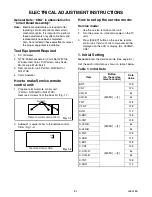
2. Flicker Adjustment
1. Enter the Service mode. (See page 5-1.)
2. Press [2] button on the remote control unit.
The following screen appears.
3. If Flicker Adjustment is not fit, the screen become
the following.
4. Press [CH
o
/
p
] buttons on the remote control
unit so that flash stops.
D2-BRT
[MENU]
→
[5]
133
D2-CNT
140
D2-CLR-R
74
D2-CLR-B
74
D2-TNT
128
D2-SHR
112
D3-BRT
[MENU]
→
[6]
126
D3-CNT
138
D3-CLR-R
64
D3-CLR-B
64
D3-TNT
128
D3-SHR
112
DR(C/D1)
[VOL
p
]
→
[4]
176
C-DR(C/D2)
157
DB(C/D1)
[VOL
p
]
→
[6]
175
C-DB(C/D2)
152
Item
Button
(on the service
remote control)
Data
Value
VCOM
110
VCOM
110
FLASH (Go and Off)
Summary of Contents for EWL20S5
Page 27: ...8 3 Main 1 5 Schematic Diagram L2601SCM1 ...
Page 28: ...8 4 L2601SCM2 Main 2 5 Schematic Diagram ...
Page 29: ...8 5 Main 3 5 Schematic Diagram L2601SCM3 ...
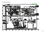
Page 30: ...8 6 L2601SCM4 Main 4 5 Schematic Diagram ...
Page 32: ...8 8 L2601SCF Function Schematic Diagram ...
Page 33: ...8 9 L2601SCIR IR Sensor Schematic Diagram ...
Page 34: ...8 10 L2601SCI Inverter Schematic Diagram ...
Page 38: ...8 14 Inverter CBA Top View BL2500F01021 Inverter CBA Bottom View ...
Page 52: ...EWL20S5 L2601UB 2006 05 29 ...


