G1
G2
G3
G4
H1
H2
H3
H4
I1
I2
I3
I4
J1
J2
J3
J4
K1
K2
K3
K4
L1
L2
L3
L4
G5
H5
I5
J5
K5
L5
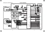
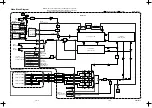
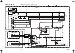
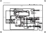
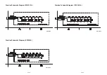
PB Audio Signal
PB Video Signal
REC Audio Signal
REC Video Signal
1-9-6
1-9-7
1-9-8
HB4J0SCM2
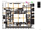
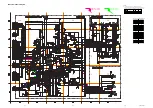
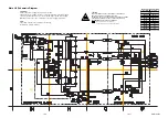
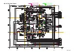
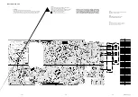
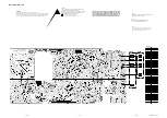
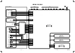
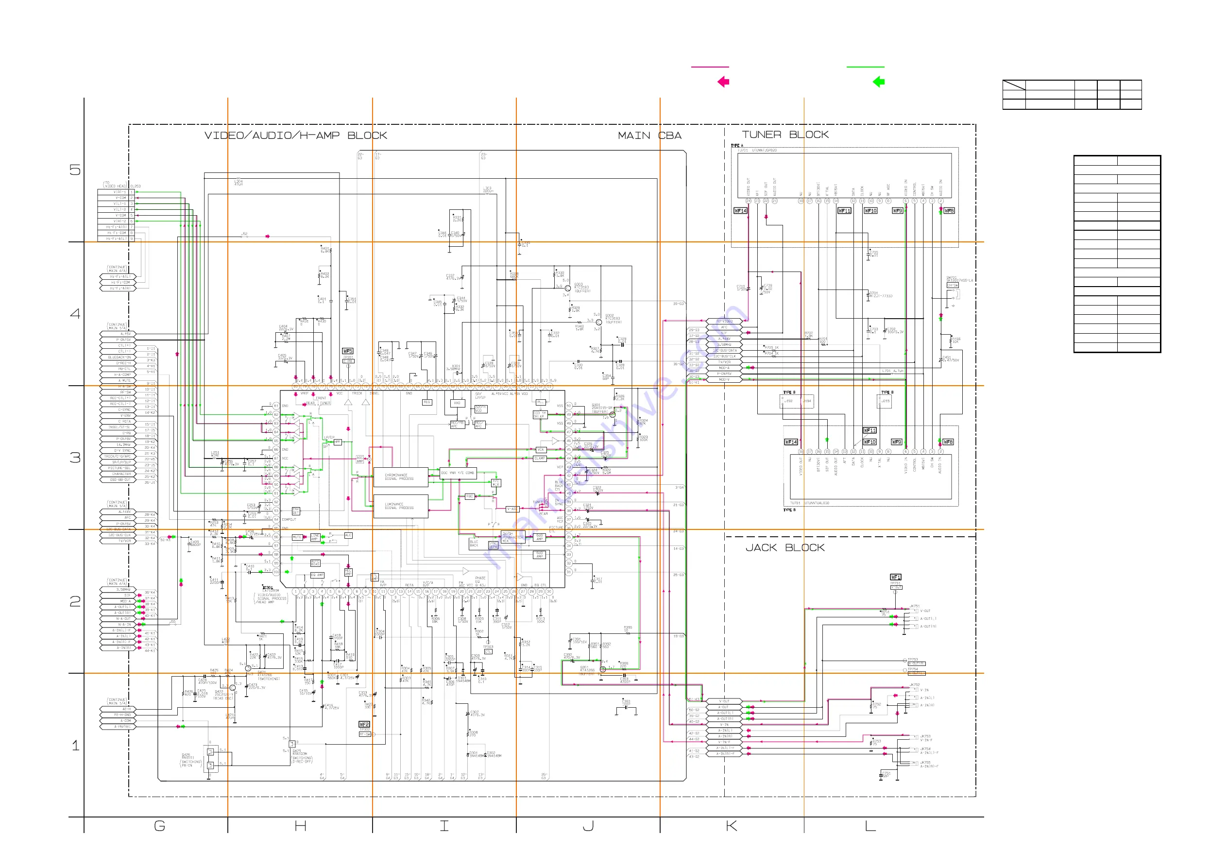
Main 2/4 Schematic Diagram
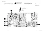
Main 2/4 Schematic Diagram
Ref.NO
Position
IC301
H-2
Q301
J-3
Q302
J-4
Q303
J-4
Q391
J-2
Q421
H-2
Q422
G-1
Q425
H-1
Q426
G-1
CL253
G-5
TP301
H-4
TP302
H-1
TP303
I-2
TP751
L-2
TP753
L-2
TP754
L-2
ICS
CONNECTORS
TEST POINTS
TRANSISTORS
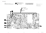
Note:
The Tuner Unit ( TU701 ) is either type A or type B.
These two types are exchangeable and can be equally used
whichever the model is. The difference between type A and
type B is shown in the table below.
*
2
TYPE B UTUNNTUAL030
TYPE A UTUNNTUSP020
J192
NU
NU
WIRE
WIRE
NU: Not Used
TU701
J194
J215
NU
WIRE

