background image


Operating instruction 

EXD-HP1/2 Controller with ModBus 

communication capability 


Emerson Climate Technologies GmbH  

www.emersonclimate.eu


Am Borsigturm 31 I 13507 Berlin I Germany 

Date: 08.09.2017 

EXD-HP12_OI_ML_R03_865921.docx 

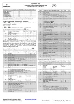
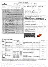
Manual alarm reset/clearing functional alarms (except hardware errors): 

Press 

 and 

 together for 5 seconds. When the clearing is done, “CL” 

message appears for 2 seconds. 

M a n u a l   m o d e   o p e r a t i o n  

Press 


and


 together for 5 seconds to access to manual mode operation. 

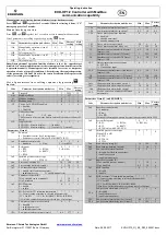
List of parameters in scrolling sequence by pressing 

 button 

Code 

Parameter description and choices 

Min 

Max 

Factory 

setting 

Field 

setting 

1Ho 

Manual mode operation; circuit 1 


0 = off;  

1 = on 


1HP 

Valve opening (%) 

100 


2Ho 

Manual mode operation; circuit 2 


0 = off  

1 = on 


2HP 

Valve opening (%) 

100 


Note:  During manual operation, functional alarms such as low superheat are 
disabled. It is recommended to monitor the system operation when the controller 
is operated manually. Manual operation is intended for service or temporary 
operation of valve at a specific condition. After achieving the required operation, 
set the parameter 1Ho and 2Ho at 0 so the controller automatically operates the 
valve(s) according to its setpoint(s). 

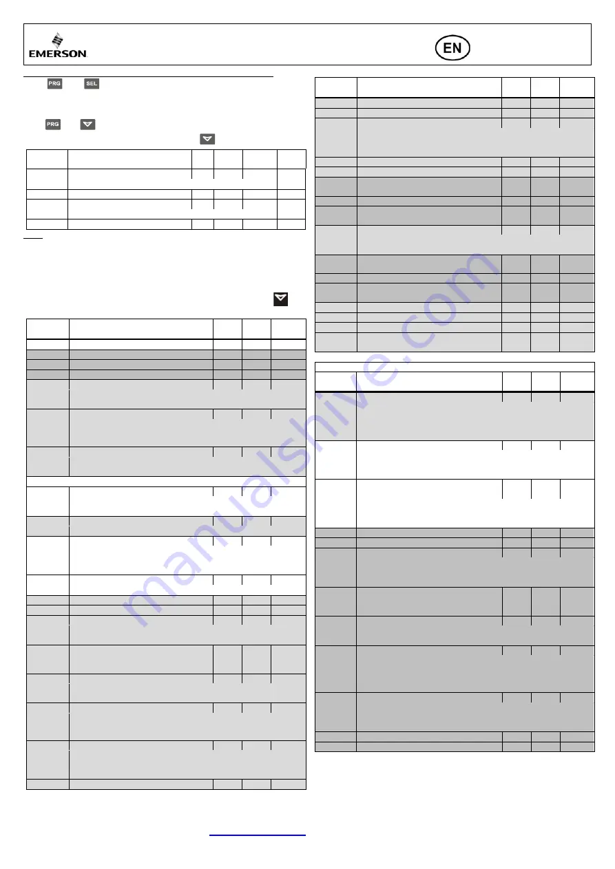
L i s t   o f   p a r a m e t e r s   i n   s c r o l l i n g   s e q u e n c e   b y   p r e s s i n g  


b u t t o n :  

Code 

Parameter description and choices 

Min 

Max 

Factory 

setting 

H5 

Password 

1999 

12 

Adr 

ModBus address 

127 

br 

Modbus baudrate 

PAr 

Modbus parity 

-C2 

Circuit 2 of EXD-HP2 enabled 

0 = Enabled;  


1 = Disabled 

-uC 

Units conversion 

0 = °C, K, bar;  

1 = F, psig 

This Parameter effects only the display. Internally the units are allways SI-
based. 

HP- 

Display mode 

EXD-HP1= 0 (not to display: - - -); 1(display) 
EXD-HP2= 0 (not to display: - - -); 1 (circuit 1); 2 (circuit2) 

Parameters Circuit 1  

1uE 

Function  

0 = Superheat control (for 6 refrigerants);  
1 = Economizer control (Only for R410A/R407C/R32) 

1u4 

Superheat control mode 

0 = Standard;  

1 = Slow    

2 = fixed PID 

1u0 

Refrigerant 

0 = R22;   

1 = R134a;  

2 = R410A; 

3 = R32 


4 = R407C; 


5 = R290


1uP 

Installed pressure sensor type  

0 = PT5-07…       1 = PT5/6-18…  

2 = PT5-30… 

1uu 

Start valve opening (%) 

10 

100 

20 

1u9 

Start opening duration (second) 

30 

1uL 

Low superheat alarm function 

0 = disable (for flooded evaporator) 
1 = enable auto reset 

2 = enable manual reset 

1u5 

Superheat set-point (K) 
If 1uL enabled (auto or manual) 
If 1uL disabled 


0.5 


30 
30 


1u2 

MOP function 

0 = disable  


1 = enable 

1u3 

MOP set-point (°C) saturation temperature 

** 

**): Factory setting according to selected refrigerant (u0): 
+13°C for R22 

+15°C for R134/R407C/R410A/R32/R290 

*) Min./Max. settings dependent on selected type of refrigerant 

1P9 

Low pressure alarm mode circuit1 

0 = disabled  
1 = enabled auto reset 


2 = enabled manual reset 

1PA 

Low pressure alarm cut-out circuit1 

-0.8 

17.7 


Code 

Parameter description and choices 

Min 

Max 

Factory 

setting 

1Pb 

Low pressure alarm delay circuit1 

199 

1Pd 

Low pressure alarm cut-in circuit1 

0.5 

18 

0.5 

1P4 

Freeze protection alarm function 

0 = disabled,  
1 = enabled auto-reset,   
2 = enabled manual reset 

1P2 

Freeze alarm cut-out circuit1 

-20 

1P5 

Freeze protection alarm delay, sec. 

199 

30 

1P- 

Superheat control circuit1 (Kp factor) 

Display 1/10K 

0.1 

10 

1.0 

1i- 

Superheat control circuit1 (Ti factor) 

350 

100 

1d- 

Superheat control circuit1 (Td factor) 

Display 1/10K


0.1 

30 

3.0 

1EC 

Hotgas temperature sensor source  

0 = ECP-P30 


1 = Via Modbus input 

1PE 

Economizer control circuit1 (Kp factor) 

Display 1/10K


0.1 

10 

2.0 

1iE 

Economizer control circuit1 (Ti factor) 

350 

100 

1dE 

Economizer control circuit1 (Td factor) 

Display 1/10K


0.1 

30 

1.0 

1uH 

High superheat alarm mode circuit 1 

1uA 

High superheat alarm setpoint circuit 1 

16 

40 

30 

1ud 

High superheat alarm delay circuit 1 

15 

1E2 

Positive correction of measured Hotgas 
temperature. 

10 


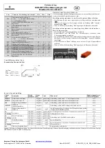
Parameters Circuit 2 (only EXD-HP2) 

Code 

Parameter description and choices 

Min 

Max 

Factory 

setting 

2u4 

Superheat control mode 

0 = Standard;  


1 = Slow;   


2 = Fix PID  

(For trouble shooting/no warranty if system to be operated with fix PID) 

2u0 

System Refrigerant 

0 = R22;   

1 = R134a;  

2 = R410A; 

3 = R32 


4 = R407C; 


5 = R290 (only with EXM/ EXL)


2uP 

Installed pressure sensor type  
(When DI2 is off) 

0 = PT5-07…        
1 = PT5/6-18…  


2 = PT5-30… 

2uu 

Start valve opening (%) 

10 

100 

20 

2u9 

Start opening duration (second) 

30 

2uL 

Low superheat alarm function 

0 = disable (for flooded evaporator) 


1 = enable auto reset 


2 = enable manual reset 

2u5 

Superheat set-point (K) 
If 2uL enabled (auto or manual) 
If 2uL disabled 


0.5 


30 
30 


2u2 

MOP function 

0 = disable  


1 = enable 

2u3 

MOP set-point (°C) saturation temperature 

** 

**): Factory setting according to selected refrigerant (2u0): 

+13°C for R22 


+15°C for R134a/R407C/R410A/R32/R290 

*) Min./Max. settings dependent on selected type of refrigerant 

2P9 

Low pressure alarm mode circuit 2 

0 = disabled  
1 = enabled auto reset 


2 = enabled manual reset 

2PA 

Low pressure alarm cut-out (bar) circuit 2 

-0.8 

17.7 

2Pb 

Low pressure alarm delay (sec) circuit 2 

199 


Summary of Contents for EXD-HP1/2

Page 1: ... waste must NOT be disposed of with other commercial waste Instead it is the user responsibility to pass it to a designated collection point for the safe recycling of Waste Electrical and Electronic Equipment WEEE directive 2012 19 EU For further information contact your local environmental recycling center E l ec tri ca l c o nne c tio n a nd w ir i ng Refer to the electrical wiring diagram for e...

Page 2: ...meter value Press or to increase or decrease the value Press to temporarily confirm the new value and display its code Repeat the procedure from the beginning press or to show To exit and save the new settings Press to confirm the new values and exit the parameters modification procedure To exit without modifying saving any parameters Do not press any button for at least 60 seconds TIME OUT Reset ...

Page 3: ...30 6 6 1u2 MOP function 0 1 1 0 disable 1 enable 1u3 MOP set point C saturation temperature Factory setting according to selected refrigerant u0 13 C for R22 15 C for R134 R407C R410A R32 R290 Min Max settings dependent on selected type of refrigerant 1P9 Low pressure alarm mode circuit1 0 2 0 0 disabled 1 enabled auto reset 2 enabled manual reset 1PA Low pressure alarm cut out circuit1 0 8 17 7 0...

Page 4: ...ally into the new controller memory The doL message appears followed by a End message for 5 seconds The new controller with new loaded parameters setting will start to operate after End message disappears Remove the key Note If the Err message is displayed for failed programming repeat the above procedure E r ro r Ala r m ha ndl i ng Alarm code Description Related parameter Alarm relay Valve What ...

Page 5: ...hen Anschluss sind die länderspezifischen Vorschriften einzuhalten Digitaleingänge sind spannungsbehaftet nur potentialfreie Schaltkontakte verwenden Entsorgung Elektro und Elektronik Altgeräte dürfen nicht mit anderem Gewerbemüll entsorgt werden Stattdessen ist es in der Verantwortung Benutzer es zu einem Sammelpunkt für die sichere Entsorgung von Elektro und Elektronik Altgeräte WEEE Richtlinie ...

Page 6: ...geschützt Das werksseitig eingestellte Passwort ist 12 Taste länger als 5 Sek gedrückt halten eine blinkende 0 erscheint oder Taste drücken bis Passwort Standardwert 12 angezeigt wird drücken Passwort wird bestätig oder Taste drücken bis der gewünschte Parameter erscheint drücken der aktuell eingestellte Wert wird angezeigt oder Taste drücken der Wert wird vergrößert oder verkleinert drücken der e...

Page 7: ...Start 10 100 20 1u9 Dauer der Ventilöffnung bei Start sec 1 30 5 1uL Alarm bei kleiner Überhitzung 0 2 1 0 aus für überfluteten Verdampfer 1 ein mit automatischer Rückstellung 2 ein mit manueller Rückstellung 1u5 Überhitzung Sollwert K wenn 1uL ein autom or manuell wenn 1uL aus 3 0 5 30 30 6 6 Code Parameter Beschreibung und Auswahl Min Max Werk 1u2 MOP Funktion 0 1 1 0 aus 1 ein 1u3 MOP Sollwert ...

Page 8: ...Am neuen Regler Versorgungsspannung ausschalten Kopierschlüssel mit den Daten des Referenzreglers einstecken dann Versorgungsspannung einschalten Die gespeicherten Daten werden automatisch in den Speicher des neuen Reglers übertragen Auf der Anzeige erscheint die Meldung doL danach 5 Sekunden lang End Nach Erlöschen der End Meldung startet der neue Regler Kopierschlüssel entfernen Hinweis Falls di...

Page 9: ...уживанием отсоедините от системы и всех её устройств напряжение питания Не запускайте систему до полного подключения всех кабелей Не подавать напряжения на контроллер до завершения электроподключения Электрические подключения необходимо производить в соответствии с законодательством Вашей страны Входы не изолированы необходимо использовать сухие контакты Утилизация Электронные и электрические отхо...

Page 10: ...новлены только когда цифровой вход DI1 DI2 выключен открыт в то время как питание включено 24 В Эта особенность нужна для дополнительной безопасности чтобы предовратить случайное повреждение компрессоров и других компонентов системы Как только главные параметры выбраны сохранены EXD HP1 2 готов к пуску Все другие параметры могут быть изменены в любое время в процессе эксплуатации по необходимости ...

Page 11: ...араметров и выборов Мин Макс Уставка завода H5 Пароль 1 1999 12 Adr ModBus адрес 1 127 1 br Modbus скорость в бодах 0 1 1 PAr Modbus четность 0 1 0 C2 Контур 2 EXD HP2 состояние 0 1 0 0 Включен 1 Отключен uC Перевод единиц 0 1 0 0 C K bar 1 F psig HP Режим отображения 0 2 1 EXD HP1 0 не отобр 1 отобр EXD HP2 0 не отобр 1 контур 1 2 контур 2 Параметры контура 1 1uE Функция Когда DI1 выкл 0 1 1 0 Пе...

Page 12: ...ные параметры с ключа на другие контроллеры Выключите питание второго контроллера Вставьте загруженный ключ с сохранёнными данными с первого контроллера во второй контроллер и включите его питание Сохранённые параметры на ключе будут загружены автоматически в память второго контроллера появится сообщение doL за ним через 5 секунд сообщение End Второй контроллер заработает с новыми загруженными пар...

Reviews: