November 2015
Installation, Operation and Maintenance Manual
RGS011110-3 Rev. 0
19
Section 4: Maintenance
Maintenance
13.
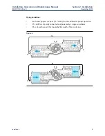
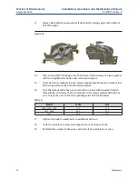
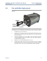
Apply a bead of Bettis approved sealant along the joining edges of the bottom
half of the body.
Figure 19
14.
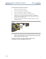
Place the top half of the body onto the bottom half and secure the two together
with the original bolts and hex nuts removed in step six.
15.
Insert both force modules into the torque module simultaneously to ensure that
both are joined correctly with the torque module.
16.
Coat the threads of the hex nuts removed in step four with medium strength
thread locker and secure the force modules to the torque module with the hex
nuts. Torque the nuts to the corresponding value in the table below.
Table 4�
Model
Ft-Lbs
Nm
2200, 2250, 2300
120
163
2375, 2488
235
318
2575
400
542
17.
Tighten the body assembly bolts an additional half turn.
18.
Cycle the actuator to ensure all components are working correctly.
19.
Reattach the actuator to the valve and reinstate the actuator to service.


