Installation, Operation and Maintenance Manual
RGS011110-3 Rev. 0
November 2015
20
Section 4: Maintenance
Maintenance
4�6
Pins and Rollers Replacement
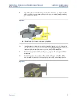
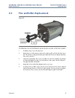
Figure 20
Pin (internal)
Body Rollers
Yoke Roller
Piston Bolt
Clevis
The following steps can be followed to replace the pins and rollers of the force modules.
1.
Complete steps 1 to 5 of Section 4.5.
2.
Apply pressure to the pressure port on the end cap (P1 or P2) of the force mod-
ule. This will cause the piston bolt to protrude from the force module and allow
the user to inspect it.
3.
Inspect the piston bolt, clevis, pin and rollers for wear. This includes any pitting,
or cracking. Replace the necessary components. Spare parts may be obtained
through your Bettis distributor.
4.
Apply heat to break the thread locker on the set screw.
5.
To replace pins or rollers remove the set screw on the top of the clevis and push
the pin through the eyes of the clevis with a punch. This may require an applica-
tion of heat as the set screw was installed with high strength thread locker.

