November 2015
Installation, Operation and Maintenance Manual
RGS011110-3 Rev. 0
3
Section 2: Installation
Installation
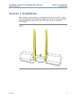
Larger sizes have lifting eyes incorporated into their body section which may be used to
lift the actuator.
Figure 2
2�1
Valve Attachment
NOTE:
Prior to mounting the actuator, verify alignment of coupler and shaft to ensure that the
valve will move to correct position.
Ensure the actuator is in the same position as the valve. It may be necessary to stroke the
actuator to determine the correct mounting orientation. Attach the actuator to the valve
using the proper bracket and coupler, or with a Bettis Universal Mounting Plate (UMP) if
provided. Using all mounting holes indicated on Bettis dimensional drawings, tighten all
fasteners hand tight then torque the fasteners to the corresponding value on the table
below.
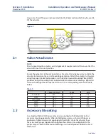
Table 1�
Thread Pattern
Ft-Lbs
Nm
Accessories
M5
3.4
4.6
F2200
M12
49
66
F2250/2300
M16
120
162
F2375
M20
235
318
F2488
M24
400
543
F2575
M30
800
1084
2�2
Accessory Mounting
As a standard, Bettis RGS F-Series actuators are provided with female 4mm slotted
accessory mounting geometry. When installing accessories, such as switch boxes or
positioners, tighten accessory mounting bolts hand tight, stroke the actuator three
times to ensure proper alignment then tighten the accessory mounting bolts to the
proper torque. Check the dimensional drawing or associated product bulletin for exact
dimensions.


