


Emerson FB1100 Flow Computer Instruction Manual
D301752X012
August 2020
14
Installation
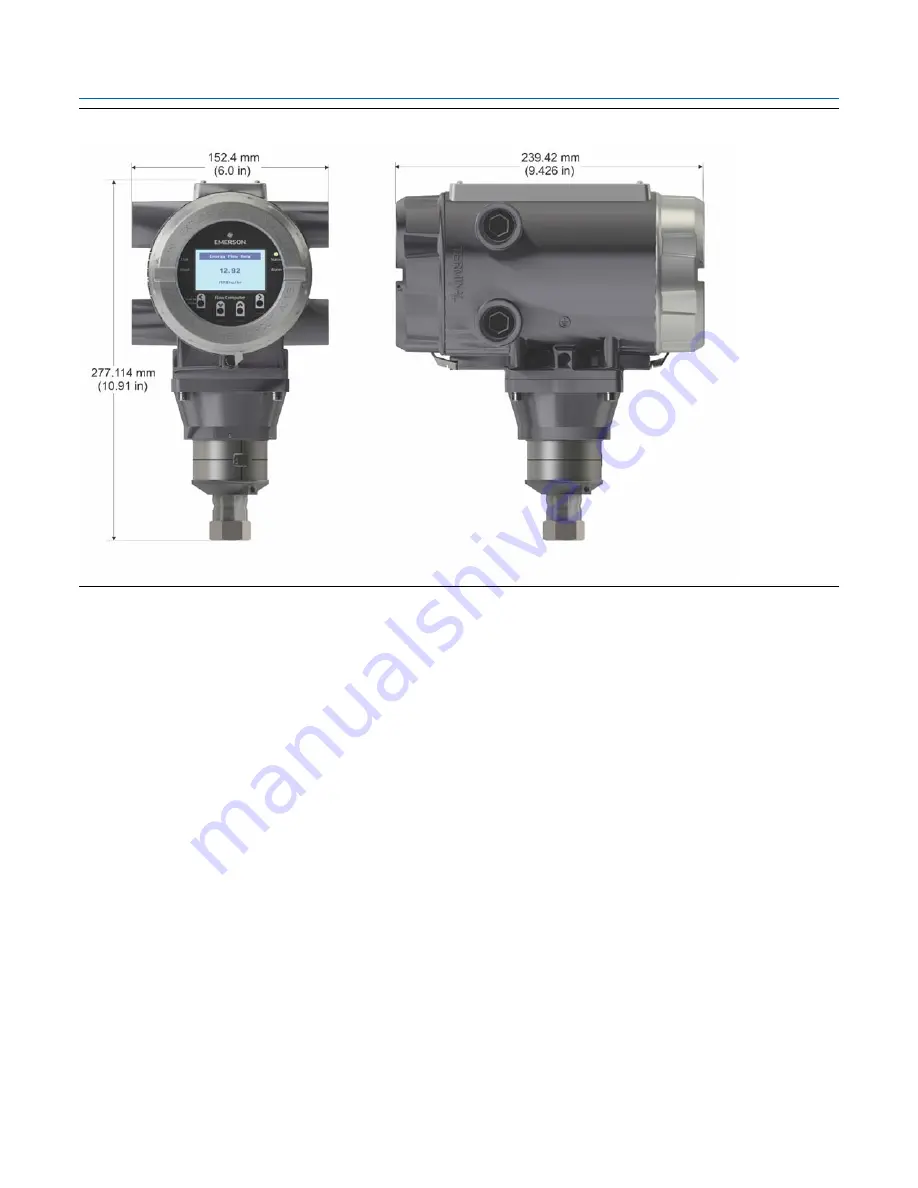
Figure 2-2: FB1100 Flow Computer Dimensions — Static Pressure Sensor
2.5
General Wiring Guidelines
The flow computer’s pluggable terminal blocks use compression-type terminals that
accommodate wire between 28 and 12 AWG.
When making a connection, insert the bare end of the wire (approx. 1/4" max) into the clamp
adjacent to the screw and secure the screw.
To prevent shorts, ensure that no bare wire is exposed.
Allow some slack in the wire while making terminal connections. Slack makes the wires more
manageable and helps minimize mechanical strain on the terminal blocks.
Use twisted pair, shielded and insulated cable for communication and I/O wiring to minimize
signal errors caused by electromagnetic interference (EMI), radio frequency interference
(RFI), and transients. When using shielded cable, ground all shields at only one point in the
appropriate system. This prevents circulating ground current loops that can cause signal
errors.
2.6
Front or Rear End Caps
The flow computer includes two threaded covers (end caps). The front end cap includes a window
for viewing the HMI module; the rear end cap provides access to the terminal plate for power and
I/O wiring.
Summary of Contents for FB1100
Page 14: ...Emerson FB1100 Flow Computer Instruction Manual D301752X012 August 2020 10 Introduction ...
Page 48: ...Emerson FB1100 Flow Computer Instruction Manual D301752X012 August 2020 44 Installation ...
Page 87: ...Emerson FB1100 Flow Computer Instruction Manual D301752X012 August 2020 Index 83 ...


