


Emerson FB1100 Flow Computer Instruction Manual
D301752X012
August 2020
20
Installation
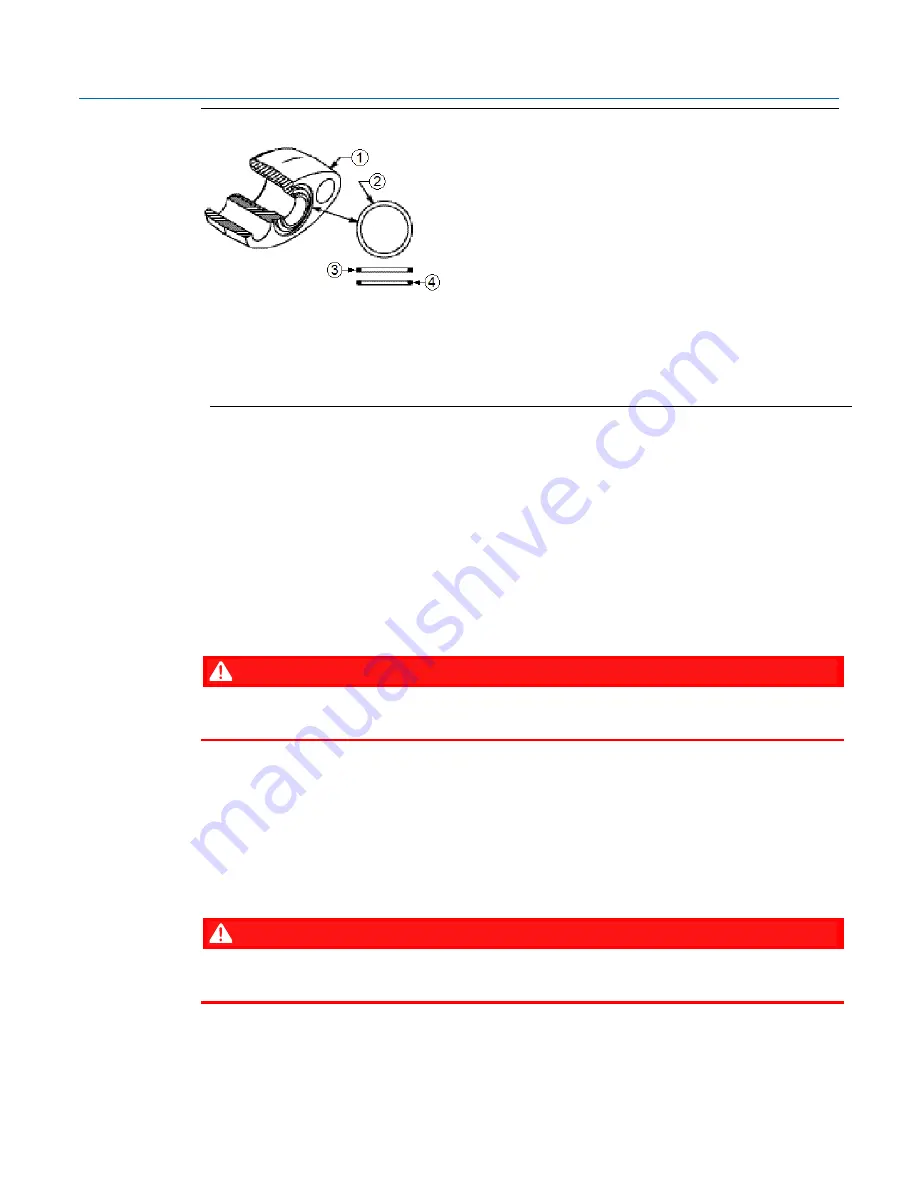
Figure 2-13: O-rings with Flange Adapters
1
Flange
2
O-ring
3
Square PTFE-based profile
4
Round Elastomer profile
1.
Whenever the flange or adapters are removed, visually inspect the O-rings.
2.
Replace the O-rings if there are any signs of damage, such as nicks or cuts.
3.
If the O-rings are replaced, re-torque the flange bolts and alignment screws after installation
to compensate for seating of the O-rings.
2.7.3
Direct Mount
Direct mount installations use either a traditional mounting kit or a coplanar mounting kit. Mount
the flow computer directly to the natural gas pipeline only if the pipeline includes a process
manifold.
DANGER
EXPLOSION HAZARD: Ensure the area in which you perform this operation is non-hazardous.
Performing this operation in a hazardous area could result in an explosion.
1.
Place taps in the top or side of the line.
2.
Mount the flow computer beside or above the taps.
2.7.4
Indirect Mount
You can mount the flow computer to a two-inch pipe or pole. Indirect mount can use the inline,
coplanar, or traditional flange mounting kits.
DANGER
EXPLOSION HAZARD: Ensure the area in which you perform this operation is non-hazardous.
Performing this operation in a hazardous area could result in an explosion.
Summary of Contents for FB1100
Page 14: ...Emerson FB1100 Flow Computer Instruction Manual D301752X012 August 2020 10 Introduction ...
Page 48: ...Emerson FB1100 Flow Computer Instruction Manual D301752X012 August 2020 44 Installation ...
Page 87: ...Emerson FB1100 Flow Computer Instruction Manual D301752X012 August 2020 Index 83 ...


