www.fisherregulators.com
D103234XUS2
Installation Guide
English – June 2011
167D Series
Maximum Operating Inlet Pressure
(1)
Types 167D and 167DS:
27,6 bar / 400 psig
Types 167DA and 167DAS:
8,6 bar / 125 psig
Types 167DA and 167DAS (NACE):
6,9 bar / 100 psig
Maximum Diaphragm Pressure
(1)
10,3 bar / 150 psig over outlet pressure setting
up to a maximum of 17,2 bar / 250 psig
Proof Test Pressure
All Pressure Retaining Components have been
proof tested per Directive 97/23/EC - Annex 1,
Section 7.4
Temperature Capabilities
(1)
Nitrile (NBR)
Standard Service (Types 167D and 167DA only):
-29° to 82°C / -20° to 180°F
Low Temperature Service (Types 167D and 167DA
only) and Standard Service (Types 167DS and
167DAS only):
-40° to 82°C / -40° to 180°F
Fluorocarbon (FKM)
High Temperature Service:
-18° to 149°C /
0° to 300°F
Installation
!
WARNING
Only qualified personnel should install
or service a switching valve. Switching
valves should be installed, operated,
and maintained in accordance with
international and applicable codes and
regulations, and Emerson Process
Management Regulator Technologies,
Inc. instructions.
If the switching valve vents fluid
or a leak develops in the system, it
indicates that service is required.
Failure to take the switching valve out
of service immediately may create a
hazardous condition.
Personal injury, equipment damage,
or leakage due to escaping fluid or
bursting of pressure-containing parts
may result if this switching valve is
overpressured or is installed where
service conditions could exceed the
limits given in the Specifications
section, or where conditions exceed
any ratings of the adjacent piping or
piping connections.
Introduction
This installation guide provides instructions for
installation, startup, and adjustment. To receive a copy
of the instruction manual, contact your local Sales
Office or view a copy at www.fisherregulators.com.
For further information refer to: Type 167D Series
Instruction Manual, Form 5859, D103234X012.
P.E.D. Category
This product may be used as a safety accessory
with pressure equipment in the following Pressure
Equipment Directive 97/23/EC categories. It may
also be used outside of the Pressure Equipment
Directive using sound engineering practice (SEP)
per table below.
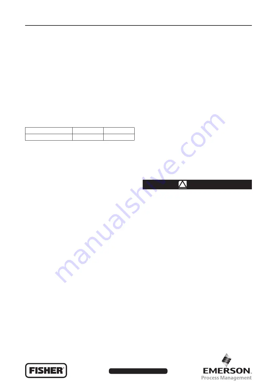
PRODUCT SIZE
CATEGORIES
FLUID TYPE
1/4 or 1/2 NPT
SEP
1
Specifications
Available Configurations
Types 167D and 167DS:
Two-way
switching valves
Types 167DA and 167DAS:
Three-way
switching valves
Body Size, Inlet and Outlet Connection Style
Ports A and C:
1/4 or 1/2 NPT
Vent and Control Pressure Connections
(Port D) and Port B:
1/4 NPT
Outlet Pressure Ranges
(1)
Types 167D and 167DS (Two-Way
Switching Valves):
Port A as Inlet:
0,21 to 1,0 bar / 3 to 15 psig
(2)
0,34 to 1,4 bar / 5 to 20 psig
0,34 to 2,4 bar / 5 to 35 psig
1,7 to 4,1 bar / 25 to 60 psig
2,8 to 8,6 bar / 40 to 125 psig
3,4 to 10,3 bar / 50 to 150 psig
(3)
Types 167DA and 167DAS (Three-Way
Switching Valves):
Port A or C as Inlet:
0,97 to 1,4 bar / 14 to 20 psig
1,1 to 2,4 bar / 16 to 35 psig
1,7 to 4,1 bar / 25 to 60 psig
2,8 to 8,6 bar / 40 to 125 psig
Port B as Inlet:
0,48 to 1,4 bar / 7 to 20 psig
0,69 to 2,1 bar / 10 to 30 psig
1,7 to 3,4 bar / 25 to 50 psig
2,8 to 6,2 bar / 40 to 90 psig
1. The pressure/temperature limits in this Installation Guide and any applicable standard or code limitation should not be exceeded.
2. For Type 167D only
3. For Type 167DS only.


