Instruction Manual
D200149X012
3610J and 3620J Positioners
September 2017
46
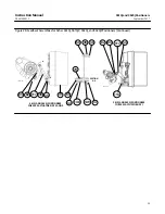
5. Install the retaining ring (key 165) and the wire tie (key 166).
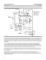
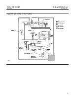
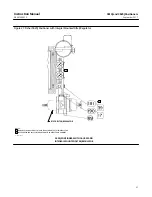
6. Assemble the bypass body (key 161) and the bypass body gasket (key 163) onto the bypass body adaptor (key 162)
with the four socket head screws (key 169). Ensure that the holes in the gasket are aligned with the holes in the
bypass body. If the gasket is installed upside down, the bypass valve will not work.
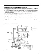
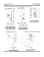
reversing plate (key 23, figure 25) with the reversing plate screw (key 49, figure 25). When installing the gasket,
make sure one of the three gasket holes is over the exhaust slot in the positioner case (key 115A, figure 25). If direct
action is required, adjust the reversing plate so the letter D is showing and the letter R is entirely covered. If reverse
action is required, adjust the reversing plate so the letter R is showing and the letter D is entirely covered. Tighten
the screw (key 49).
8. If the input module is removed, perform the Assembling the Input Module procedure.
9. Plug the relay A and relay B output connections and apply 2.4 bar (35 psig) to the Instrument connection. Using
soap solution or some other solution compatible with Nitrile rubber, check the bypass assembly for leaks at the
gasket and O‐ring seals while rotating the bypass lever to both BYPASS and POSITIONER.
Changing Positioner Types
Changing a 3610J to a 3610JP Positioner, Changing a 3620J to a 3620JP Positioner, or Vice Versa:
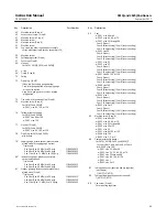
referring to figure 7. Refer to the Disassembling the Nozzle Assembly and Assembling the Nozzle Assembly
maintenance procedures.
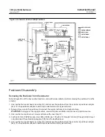
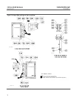
instrument gauge (key 80, figure 26) depending on the instrument input signal. Apply sealant (key 154) to the
threads of the gauges.
and size. Refer to keys 117, 170, 171, 75, 76, 77, and 99 in the parts list. To change from key 117 to 170, or vice
versa, refer to the Disassembling the Feedback Lever Assembly and Assembling the Feedback Lever Assembly
maintenance procedures.
two screws (key 83, figure 28) may also be required and possibly a cam adjustment indicator (key 84, figure 28).
The cam adjustment indicator is only used with the characterized cams B or C. Refer to the Changing Cams
procedure.
6. A positioner adaptor may be required depending on actuator type and size. Refer to key 113 in the parts list. If the
Apply sealant (key 154) to the threads of the pipe plugs.
Changing a 3610JP to a 3611JP Positioner, Changing a 3620JP to a 3621JP Positioner, or Vice
Versa:
Lever Assembly and Assembling the Feedback Lever Assembly maintenance procedures.
2. Changing from a 3610JP to a 3611JP or a 3620JP to a 3621JP requires the following feedback parts: keys 172, 173,
174, 175, 184 (585 size 100 actuator only), and 185 [585 size 100 actuator with 51 through 102 mm (2 through 4
inch) travels only, see figure 29].
3. Changing from a 3610JP to a 3611JP, or a 3620JP to a 3621JP requires installing a parallel flexure (key 179, figure

