Instruction Manual
D200149X012
3610J and 3620J Positioners
September 2017
23
WARNING
During calibration the valve may move. To avoid personal injury or property damage caused by the release of pressure or
process fluid, provide some temporary means of control for the process.
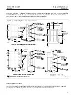
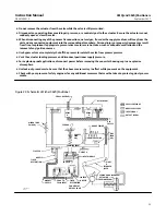
Refer to figure 25 for key number locations. Adjustments are shown in figure 13.
Minor Loop Gain Adjustment
The minor loop gain adjustment varies the dynamic gain of the positioner to match the specific size and characteristic
of the actuator. This adjustment allows tuning of the positioner transient response to the application without
significantly affecting the static operating performance.
The minor loop gain adjustment is factory set for a positioner shipped with the actuator. However, additional
adjustment should be made to suit the particular application requirement. The minor loop gain also may require
adjustment if:
D
the positioner was not installed on the actuator by the factory,
D
installing the positioner on an actuator other than the type for which the positioner was originally set up,
D
maintenance was performed on the positioner.
The minor loop gain should be adjusted before performing the other calibration procedures.
Figure 13 shows the minor loop gain adjustment location. As shown in figure 14, the adjustment is made by moving
the flexure adjustment (key 156) along the top flexure.
Figure 13. Calibration Adjustments
ZERO ADJUSTMENT
(KEY 143)
3610J, 3610JP, 3620J, AND 3620JP POSITIONERS
W4900‐1
SUMMING BEAM
(KEY 123)
COARSE SPAN
ADJUSTMENT
RANGE SPRING
(KEY 150)
FINE SPAN
ADJUSTMENT
(KEY 128)
RANGE SPRING
HANGER (KEY 130)
CROSSOVER ADJUSTMENT
(KEY 13)
MINOR LOOP GAIN
ADJUSTMENT (KEY 156)
DIRECT/REVERSE
PLATE (KEY 23)
3611JP AND 3621JP POSITIONERS
W4901‐1
SOCKET HEAD
SCREW AND WASHER
(KEYS 180 AND 181)
PARALLEL
FLEXURE
(KEY 179)


