Instruction Manual
D200149X012
3610J and 3620J Positioners
September 2017
27
Table 11. Fisher 3621JP Positioner Range Spring Selection and Coarse Span Adjustment
Valve Travel
mm (Inches)
Input Span
16 mA
5.3 mA
8 mA
Range Spring
Hole Number
Range Spring
Hole Number
Range Spring
Hole Number
11 (0.4375)
Blue
4
Red
1
Red
2
14 (0.5625)
Blue
4
Red
1
Red
2
19 to 51 (0.75 to 2)
Blue
3
Yellow
1
Yellow
2
51 to 102 (2 to 4)
Blue
3
Yellow
1
Yellow
2
1. For positioners mounted on 585, 585R, 585C, and 585CR actuators.
2. This table is only valid for the valve travel and range spring combinations listed. Contact your
for travels or input spans not shown for the valve travel/range spring
combination.
3. For the 585 actuator, size 100 only
Note
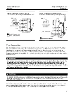
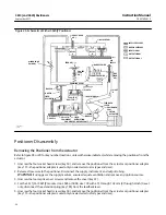
Figure 15. Span Adjustment
20B1277‐E
A3232‐2
SUMMING BEAM
ASSEMBLY
(KEY 123)
COARSE SPAN
ADJUSTMENT
FINE SPAN ADJUSTMENT
(KEY 128)
FEEDBACK LEVER ASSEMBLY
(KEY 117)
RANGE SPRING HANGER
(KEY 130)
RANGE SPRING
(KEY 150)
#5
#4
#3
#2
#1
3. Apply supply pressure.
4. Apply an input signal equal to the low value of the input signal range; for example, if the input signal range is 0.2 to
1.0 bar (3 to 15 psig), apply 0.2 bar (3 psig.)
down depending on the action selected) corresponding to the low input signal. Clockwise rotation of the zero
adjustment screw retracts the actuator stem.
6. Slowly increase the input signal toward the high end of the input signal range and observe the actuator stroke. If the
actuator stroke is short of its expected range, increase the travel by rotating the fine span adjustment screw (key
128, figure 13) counterclockwise with a screwdriver. If the actuator reaches the end of its desired travel with an
input signal less than the high value of the input signal range, decrease the travel by rotating the fine span
adjustment screw clockwise with a screwdriver.
7. Repeat steps 4, 5, and 6 until the actuator stroke corresponds to the input signal range.
8. Replace the cover on the positioner.
Changing Positioner Action
This section explains how to change the positioner action from direct to reverse or reverse to direct. With direct
action, the actuator stem extends as the input signal to the positioner increases. With reverse action, the actuator
stem retracts as the input signal to the positioner increases.


