3660 and 3661 Positioners
Instruction Manual
Form 5265
March 2006
14
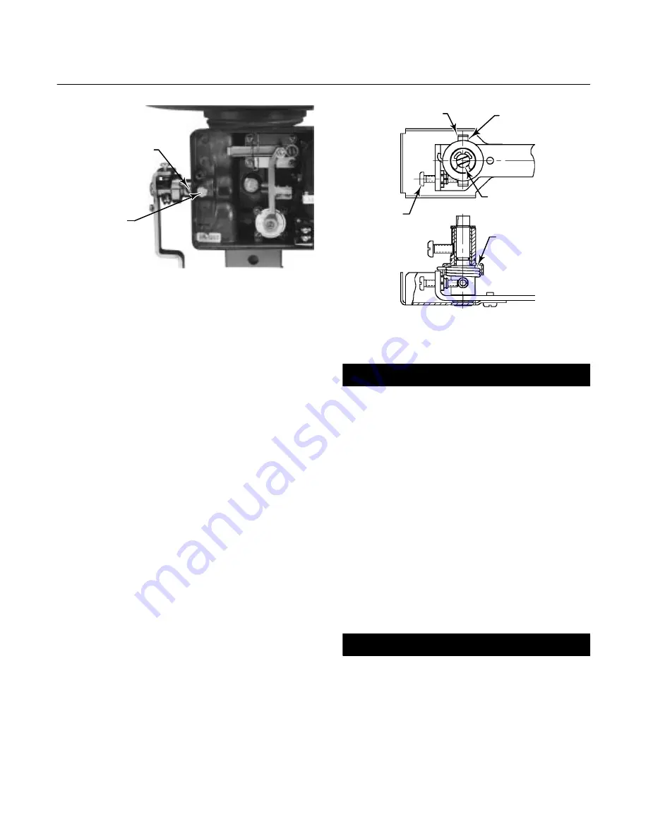
RETAINING SCREW
(KEY 19P)
ANTI-ROTATING
SLOT
W7367 / IL
Figure 9. Installing the Feedback Lever Assembly
(Key 19) on the Positioner
lever assembly and feedback arm are horizontal and
that the feedback lever assembly and the feedback
arm are parallel with each other. If necessary,
correct alignment by loosening the hex nuts (keys 86
and 90) and either moving the stud clamp in the
mounting bracket or moving the mounting bracket on
the actuator leg.
10. Tighten the nuts that were not tightened in the
previous steps.
a. Tighten the hex nut (key 90) to secure the
positioner to the stud clamp (key 83).
b. Tighten the four hex nuts (key 86) to secure
the mounting bracket (key 82) to the actuator leg.
c. Tighten the machine screws and hex nuts (key
91 and 93) to secure the feedback arm (key 88)
to the connector bracket (key 87).
d. Tighten the hex head screws (key 69) to
secure the connector bracket (key 87) to the
actuator stem connector.
11. Install the feedback lever assembly and range
spring.
Feedback Lever Assembly and Range
Spring Installation
Key numbers are shown in either figure 24 for the
Type 3660 positioner or figure 25 for the Type 3661
positioner. Key numbers for the feedback lever
assembly are shown in figure 26.
ZERO
ADJUSTMENT
COVER
FEEDBACK
SHAFT
SPRING PIN
FEEDBACK SPRING
FEEDBACK SPRING MUST
HOOK AROUND SPRING PIN
END OPPOSITE THE ZERO
ADJUSTMENT SCREW
27B9999-D
A7224 / IL
Figure 10. Positioning Feedback Spring
CAUTION
The range spring (key 30) and
feedback lever assembly (key 19) must
be installed together. Installing the
range spring after the feedback lever
assembly is installed may result in
damage to the lever assembly (key 17)
flexures.
1. Refer to figure 9. Loosen the retaining screw
(key 19P) located in the positioner housing until it is
fully retracted into the housing.
2. On the feedback lever assembly (key 19), loosen
the zero adjustment screw (key 19S) until it is fully
retracted into the clinch nut.
3. On the feedback lever assembly, loosen the hex
nut (key 19D) so the pilot shaft (key 19A) moves
freely in the slot.
CAUTION
In the next step, be sure the feedback
spring (key 19N) hooks on the spring
pin (key 19R) opposite the zero
adjustment screw. If the feedback
spring does not hook on the spring pin
correctly, the feedback spring may be
damaged during feedback lever
assembly (key 19) installation.


