Instruction Manual
D101728X012
3710 and 3720 Positioners
September 2017
47
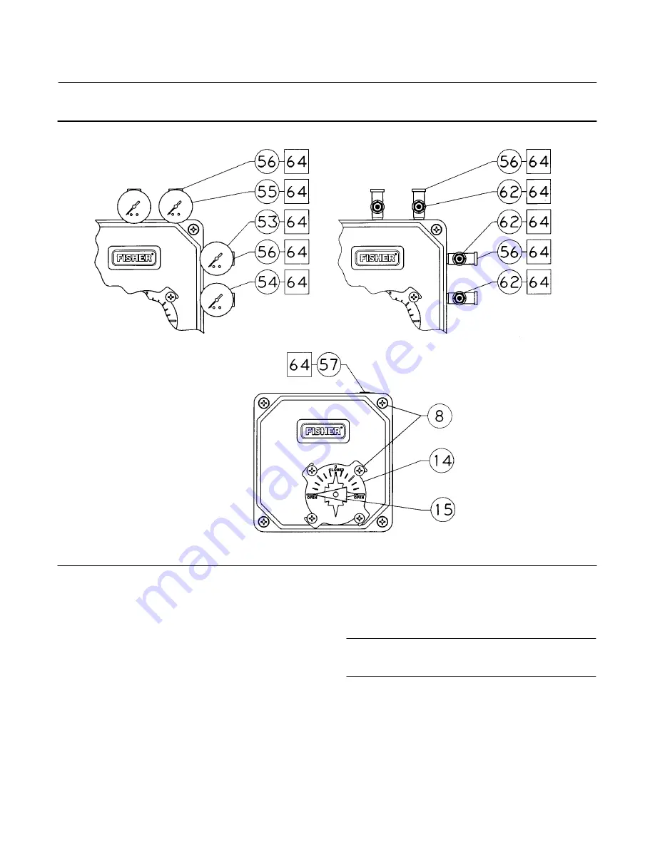
Figure 31. Fisher 3710 Components and Subassemblies (continued)
42B7272 SHT 3 OF 3
3710 WITH GAUGES
3710 WITH TIRE VALVES
3710 WITH STANDARD LOW‐PROFILE INDICATOR
V
ADD LUBE
Key
Description
28
Action block
29*
Action block gasket
30*
Input module assy
Includes summing beam assy and flexure
31*
O‐ring
For use between input module assy and
positioner base plate
32
Zero adjustment pivot
33
Washer (metric)
For zero adjustment pivot
Key
Description
34
Retaining ring (E‐clip) (metric)
For zero adjustment pivot
Note
Two zero adjusters (key 35) are required: one for the zero adjustment
locknut and one for the zero adjustment knob.
35
Zero adjuster(2 req'd)
36*
Cam
Rotary Valves, std 90 deg rotation
Sliding‐Stem Valves
37
Cam locknut (hex/metric)
*Recommended spare parts
1. Also recommended as a spare if metric
fasteners are not available at the installation site.


