Instruction Manual
D101728X012
3710 and 3720 Positioners
September 2017
36
4. Inspect the feedback tie bar (key 42) attached to the actuator hub. If necessary, unscrew the machine screws
(key 47) and remove the tie bar.
Removing the Feedback Arm Assembly
1. Unscrew the cam locknut (key 37) and remove the cam (key 36).
Note
The zero adjustment locknut and zero adjustment knob are identical parts, key 35.
2. Loosen the zero adjustment locknut and turn the zero adjustment knob (key 35) until the range spring is free from
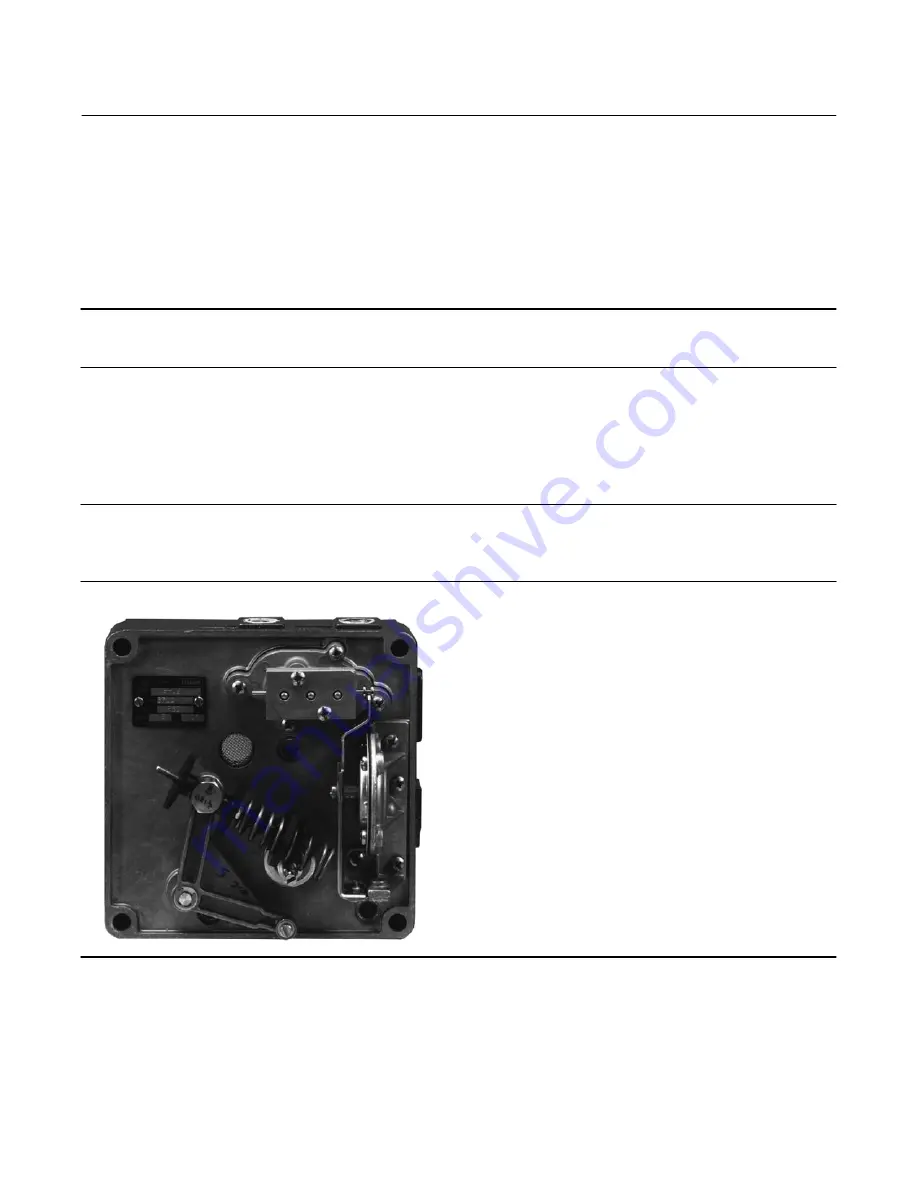
the summing beam. See figure 25. Move the feedback arm (key 21) until the range spring falls away from the
summing beam.
Note
The feedback pivot cannot be removed from the positioner base plate.
Figure 25. Cam Removed; Range Spring Free
From Summing Beam
W6062
3. Remove the retaining ring (E‐clip) (key 27) which holds the feedback arm (key 21) onto the feedback pivot. Remove
the washer under the retaining ring and pull the feedback arm from the pivot.
4. Remove the flanged bearing (key 22) from the feedback pivot or from the feedback arm. Inspect and replace the
bearing, if necessary.


