Instruction Manual
D103425X012
546NS Transducer
June 2021
21
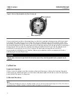
Figure 7. Transducer Assembly
FILTER REGULATOR
TORQUE MOTOR
FLAME ARRESTOR
82 RELAY
FLAME
ARRESTOR
APPLY LUBRICANT/SEALANT
NOTE: KEY 4 NOT SHOWN
30A8595‐L
B1768‐3
Key
Description
Torque Motor (figure 8)
15
(1)
Adjusting Screw
16
(1)
Spring Seat
17
(1)
Spring‐Zero Adjustment (SST)
18
(1)
Baffle
19
(1)
Nozzle
20
(1)
Hook‐Up Wire Ass'y
21
(1)
Hook‐Up Wire Ass'y
22
(1)
Hook‐Up Wire (not shown)
25
(1)
Machine Screw
26
(1)
Screw
27
(1)
Cap Screw
Key
Description
28
(1)
Machine Screw
29
(1)
O‐Ring
31
Hex Nut
32
(1)
Washer
33
Washer
34
(1)
Washer
35
(1)
Washer
36*
O‐Ring (2 req'd)
37*
O‐Ring
38
(1)
E‐Ring
40
(1)
Armature
41
(1)
Coil Support
42
(1)
Coil Ass'y
48
(1)
Magnet
49
(1)
Pole Piece
50
(1)
Top Pole Piece Plate
*Recommended spare parts
1. Parts are not field repairable. The torque motor assembly should never be
disassembled because the magnetism in the torque motor will decrease
permanently. Shaded key numbers shown in figure 8 indicate parts that should not
be disassembled.

