Instruction Manual
D101351X012
646 Transducer
January 2015
17
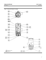
2. Insert the assembled valve plug, inner valve spring, and body plug into the relay body (key 1). Compress the spring
and thread the body plug (key 5) into place. Then, tighten the body plug.
3. Insert two of the mounting screws (key 7) into two opposite holes of the relay body (key 1). Hold the screws in place
while assembling the following parts on the relay body. The screws serve as studs to align the parts as they are being
assembled.
4. When replacing the exhaust port assembly (key 10), make sure all passages and screw holes are aligned and that
the hole in the center of the exhaust port assembly fits over the valve plug (key 14). Place the exhaust port assembly
on the relay body (key 1). Hold assembled parts in place.
5. Make sure the tabs on the body block (key 2) align with the tabs on the relay body (key 1) and that the side with 5
holes faces the relay body. Place the body block on the assembled parts. Hold assembled parts in place.
6. When replacing the input diaphragm (key 9), make sure all passages and screw holes are aligned. Place the input
diaphragm on the body block (key 2). Hold assembled parts in place.
7. Install the bias spring (key 13) into the transducer housing assembly (key 3). Make sure the tabs on the body block
and relay body align with the tab on the transducer housing assembly. Place the assembled parts onto the
transducer housing assembly. Thread the two mounting screws (key 7) into the transducer housing assembly.
Install the remaining two mounting screws. Tighten all mounting screws to 2 N
S
m (20 lbf
S
in).
8. Perform the procedures in the Calibration section.


