Instruction Manual
D101351X012
646 Transducer
January 2015
3
Table 1. Specifications (Continued)
Mounting Position
Any position is acceptable for standard pipestand,
panel, or actuator mounting. For weatherproof
housing, mount the transducer so the vent can drain.
Approximate Weight (Transducer Only)
1.6 kg (3.5 pounds)
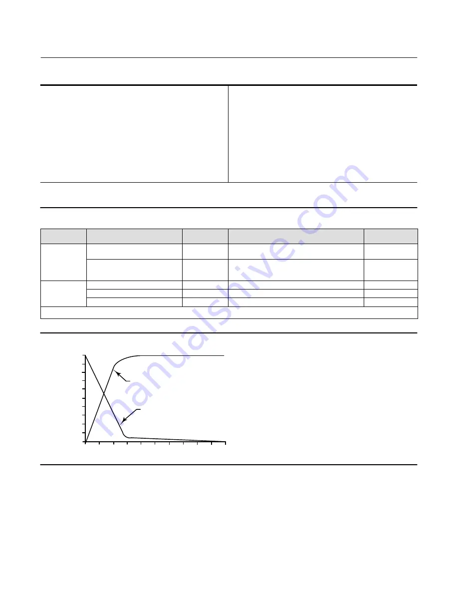
Actuator Stroking Time
See figure 2
Declaration of SEP
Fisher Controls International LLC declares this
product to be in compliance with Article 3 paragraph
3 of the Pressure Equipment Directive (PED) 97 / 23 /
EC. It was designed and manufactured in accordance
with Sound Engineering Practice (SEP) and cannot
bear the CE marking related to PED compliance.
However, the product
may
bear the CE marking to
indicate compliance with
other
applicable European
Community Directives.
NOTE: Specialized instrument terms are defined in ANSI/ISA Standard 51.1 ‐
Process Instrument Terminology.
1. The pressure and temperature limits in this document and any applicable standard or code limitation should not be exceeded.
2. Normal m
3
/hr—Normal cubic meters per hour (0
_
C and 1.01325 bar, absolute). Scfh—Standard cubic feet per hour (60
_
F and 14.7 psia).
3. Average flow rate determined at 12 mA and 0.6 bar (9 psig) output.
4. Performance values are obtained using a transducer with a 4 to 20 mA DC input signal and a 0.2 to 1.0 ba (r3 to 15 psig) output signal at an ambient temperature of 24
_
C (75
_
F).
Table 2.
EMC Summary Results—Immunity
Port
Phenomenon
Basic Standard
Test Level
Performance
Criteria
(1)
Enclosure
Electrostatic discharge (ESD)
IEC 61000‐4‐2
4 kV contact
8 kV air
A
Radiated EM field
IEC 61000‐4‐3
80 to 1000 MHz @ 10V/m with 1 kHz AM at 80%
1400 to 2000 MHz @ 3V/m with 1 kHz AM at 80%
2000 to 2700 MHz @ 1V/m with 1 kHz AM at 80%
A
I/O signal/control
Burst (fast transients)
IEC 61000‐4‐4
1 kV
A
Surge
IEC 61000‐4‐5
1 kV (line to ground only, each)
B
Conducted RF
IEC 61000‐4‐6
150 kHz to 80 MHz at 3 Vrms
A
1. A = No degradation during testing. B = Temporary degradation during testing, but is self‐recovering.
Specification Limit = +/‐ 1% of span.
Figure 2. Output‐Time Relationships for Fisher 646 Transducer
LOADING
EXHAUSTING
TIME (%)
0
10
20
30
40
50
60
70
80
90
100
0
10
20
30
40
50
60
70
80
90
100
OUTPUT
(% OF 646 OUTPUT SPAN)
A6815 / IL
Description
The transducer, shown in figure 1, receives a 4-20 milliampere DC input signal and transmits a proportional 0.2 to 1.0
bar (3 to 15 psig) pneumatic output pressure to a final control element. A typical application is in electronic control
loops where the final control element is a control valve assembly that is pneumatically operated. The input signal and
output pressure range of the transducer is indicated on the nameplate attached to the housing.


