background image

S201 and S202 Series

2

Specifications

Principle of Operation

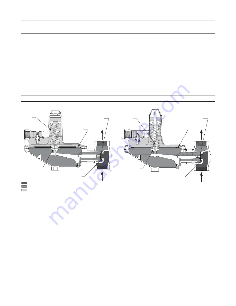
Refer to Figure 2.  When downstream demand 

decreases, the pressure under the diaphragm 

increases.  This pressure overcomes the regulator 

setting (which is set by the control spring).  Through 

the action of the pusher post assembly, lever, and 

valve stem, the valve disk moves closer to the orifice 

and reduces gas flow.  If demand downstream 

increases, pressure under the diaphragm decreases.  

Spring force pushes the pusher post assembly 

downward, and the valve disk moves away from the 

orifice, and the gas flow increases.

The Types S202 and S202H regulators include an 

internal relief valve.  Internal relief is used to help 

minimize overpressure.  Any outlet pressure above 

the start-to-discharge point of the non-adjustable relief 

spring moves the diaphragm off of the relief seat, 

allowing excess pressure to discharge through the vent.  

Typical start-to-discharge values are 7-inches w.c. to  

2 psi (17 to 138 mbar) above the outlet pressure 

setting, depending on control spring used.

Available Configurations 


See Figure 3

Body Size and End Connection Styles

1-1/2 or 2 NPT inlet and outlet and 

NPS 2 (DN 50) CL125 FF flanged

Maximum Allowable Inlet Pressures

(1)

See Table 1

Maximum Emergency Outlet Pressure

(1)

15 psig (1,0 bar)                  

Outlet Pressure Range

2.0-inches w.c. to 10 psig (5 mbar to 0,69 bar)

Orifice Size

1/4, 3/8, 1/2, 3/4, 1, and 1-3/16-inches 

(6,4; 9,5; 13; 19; 25; and 30 mm) 

Temperature Capabilities

-20° to 150°F (-29° to 66°C)

Pressure Registration

Internal

Approximate Weight

22 pounds (10 kg)

  1.  The pressure/temperature limits in this Instruction Manual and any applicable standard or code limitation for valve should not be exceeded.

INLET PRESSURE

OUTLET PRESSURE

ATMOSPHERIC PRESSURE

A6198

Type S202

Figure 2.  Operational Schematics

A6197

A6198

INLET PRESSURE
OUTLET PRESSURE
ATMOSPhERIC PRESSURE

CONTROL

SPRING

RELIEF vALvE 

SPRING

PUShER POST

PUShER POST

DIAPhRAGM

DIAPhRAGM

vALvE DISk

vALvE DISk

ORIFICE

ORIFICE

TyPE S201

TyPE S202

Summary of Contents for Fisher S202

Page 1: ...ulator Warning Figure 1 Typical S200 Gas Regulator W1919 Introduction Scope of the Manual This instruction manual provides instructions for installation adjustment maintenance and parts ordering information for Types S201 S201H S201K S202 and S202H gas service regulators Description S201 and S202 Series regulators are typically installed on industrial and commercial applications The Types S202 and...

Page 2: ...Typical start to discharge values are 7 inches w c to 2 psi 17 to 138 mbar above the outlet pressure setting depending on control spring used Available Configurations See Figure 3 Body Size and End Connection Styles 1 1 2 or 2 NPT inlet and outlet and NPS 2 DN 50 CL125 FF flanged Maximum Allowable Inlet Pressures 1 See Table 1 Maximum Emergency Outlet Pressure 1 15 psig 1 0 bar Outlet Pressure Ran...

Page 3: ...utdoor installations point the spring case vent downward to allow condensate to drain see Figure 4 This minimizes the possibility of freezing and of water or other foreign materials from entering the vent and interfering with proper operation Under enclosed conditions or indoors escaping gas may accumulate and be an explosion hazard In these cases the vent should be piped away from the regulator t...

Page 4: ...le 2 Outlet pressure more than 2 psi 0 14 bar light diaphragm head or 3 psi 0 21 bar heavy diaphragm head above the setpoint may damage internal parts such as the diaphragm head and valve disk The maximum emergency casing outlet pressure is 15 psig 1 0 bar Startup caution Pressure gauges should always be used to monitor downstream pressure during startup Procedures used in putting this regulator i...

Page 5: ...pressure and relieving all internal pressure as described in Shutdown Regulators that have been disassembled for repair must be tested for proper operation before returned to service Only parts manufactured by Emerson Process Management Regulator Technologies Inc should be used for repairing Fisher regulators Relight pilot lights according to normal startup procedures Due to normal wear or damage ...

Page 6: ... tear the diaphragm when reassembling 6 Reassemble the spring case unit in the reverse order of the above steps Before tightening the cap screw or stem into the pusher post place the loosely assembled diaphragm and diaphragm head assembly into position in the lower casing being sure that the pusher post is hooked on the lever Rotate the diaphragm so that the diaphragm and lower casing holes are al...

Page 7: ... and S202 Series 7 Figure 5 Type S202 Regulator Assembly 50A9455 parts not shown 46 apply LUB SEA ADH section a a A A VENT 62 61 58 55 60 56 57 59 18 4 5 3 2 6 8 9 7 1 32 14 15 10 25 16 13 21 20 19 12 11 24 ...

Page 8: ... Management Regulator Technologies Inc USA Headquarters McKinney Texas 75069 1872 USA Tel 1 800 558 5853 Outside U S 1 972 548 3574 Asia Pacific Singapore Singapore 128461 Tel 65 6777 8211 Europe Bologna Italy 40013 Tel 39 051 4190611 Gallardon France 28320 Tel 33 0 2 37 33 47 00 TESCOM Emerson Process Management Tescom Corporation USA Headquarters Elk River Minnesota 55330 2445 USA Tel 1 763 241 ...

Reviews: