background image

S201 and S202 Series

3

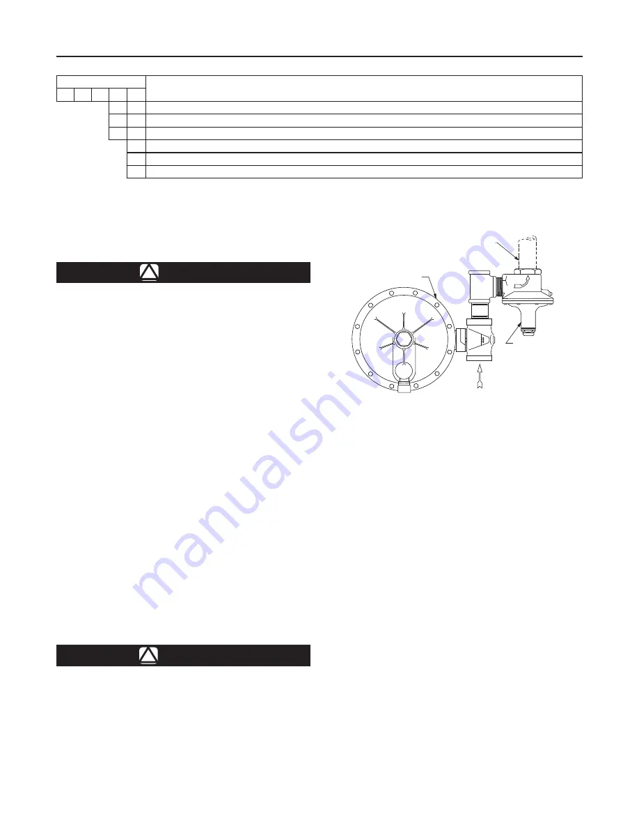
Figure 4.  Type S201 Regulator Installed with the Vent 

Pointed Downward and with a Type 289H Relief Valve for 

High Capacity Relief

AJ4698

A1121

PROTECT vENT PIPE 

WITh RAIN CAP

NPS 2 (DN 50) 

TyPE 289h 

RELIEF vALvE

TyPE S201 

REGULATOR

TyPE NUMBER

OPTIONS

S

2

0

REGULATOR TyPE

1

Regulator, 2 to 30-inches w.c. (5 to 75 mbar) outlet range

2

Regulator, 2 to 30-inches w.c. (5 to 75 mbar) outlet range with Internal Relief

PRESSURE OUTLET RANGE

H

High-Pressure Regulator, 1 to 5 psi (0,07 to 0,34 bar) outlet range with heavy diaphragm plate

K

High-Pressure Regulator with external adjusting screw, 2 to 10 psi (0,14 to 0,69 bar) outlet range (Not an option for S202)

Figure 3.  Available Configurations

Installation

!

WARNING

Personal injury or system damage 

may result if this regulator is installed, 

without appropriate overpressure 

protection, where service conditions 

could exceed the limits given on the 

Specifications section and regulator 

nameplate.  Regulator installations 

should be adequately protected from 

physical damage.
All vents should be kept open to permit 

free flow of gas to the atmosphere.  

Protect openings against entrance of 

rain, snow, insects, or any other  foreign 

material that may plug the vent or vent 

line.  On outdoor installations, point the 

spring case vent downward to allow 

condensate to drain (see Figure 4).  This 

minimizes the possibility of freezing and 

of water or other foreign materials from  

entering the vent and interfering with 

proper operation.
Under enclosed conditions or indoors, 

escaping gas may accumulate and be 

an explosion hazard.  In these cases, 

the vent should be piped away from the 

regulator to the outdoors.

CAUTION

S201 and S202 Series regulators have 

an outlet pressure rating lower than 

their inlet pressure rating.  If actual inlet 

pressure can exceed the outlet pressure 

rating, outlet overpressure protection 

is necessary.  however, overpressuring 

any portion of the regulators beyond the 

limits in the Specifications section and 

Table 1 may cause leakage, damage to 

regulator parts, or personal injury due to 

bursting of pressure-containing parts.
Some type of external overpressure 

protection should be provided if inlet 

pressure will be high enough to damage 

downstream equipment.  Common 

methods of external overpressure 

protection include relief valves, 

monitoring regulators, shutoff devices, 

and series regulation.
If the regulator is exposed to an 

overpressure condition, it should be 

inspected for any damage that may 

have occurred.  Regulator operation 

below these limits specified in the 

Specifications section and Table 1 does 

not preclude the possibility of damage 

from external sources or from debris in 

the pipeline.

Summary of Contents for Fisher S202

Page 1: ...ulator Warning Figure 1 Typical S200 Gas Regulator W1919 Introduction Scope of the Manual This instruction manual provides instructions for installation adjustment maintenance and parts ordering information for Types S201 S201H S201K S202 and S202H gas service regulators Description S201 and S202 Series regulators are typically installed on industrial and commercial applications The Types S202 and...

Page 2: ...Typical start to discharge values are 7 inches w c to 2 psi 17 to 138 mbar above the outlet pressure setting depending on control spring used Available Configurations See Figure 3 Body Size and End Connection Styles 1 1 2 or 2 NPT inlet and outlet and NPS 2 DN 50 CL125 FF flanged Maximum Allowable Inlet Pressures 1 See Table 1 Maximum Emergency Outlet Pressure 1 15 psig 1 0 bar Outlet Pressure Ran...

Page 3: ...utdoor installations point the spring case vent downward to allow condensate to drain see Figure 4 This minimizes the possibility of freezing and of water or other foreign materials from entering the vent and interfering with proper operation Under enclosed conditions or indoors escaping gas may accumulate and be an explosion hazard In these cases the vent should be piped away from the regulator t...

Page 4: ...le 2 Outlet pressure more than 2 psi 0 14 bar light diaphragm head or 3 psi 0 21 bar heavy diaphragm head above the setpoint may damage internal parts such as the diaphragm head and valve disk The maximum emergency casing outlet pressure is 15 psig 1 0 bar Startup caution Pressure gauges should always be used to monitor downstream pressure during startup Procedures used in putting this regulator i...

Page 5: ...pressure and relieving all internal pressure as described in Shutdown Regulators that have been disassembled for repair must be tested for proper operation before returned to service Only parts manufactured by Emerson Process Management Regulator Technologies Inc should be used for repairing Fisher regulators Relight pilot lights according to normal startup procedures Due to normal wear or damage ...

Page 6: ... tear the diaphragm when reassembling 6 Reassemble the spring case unit in the reverse order of the above steps Before tightening the cap screw or stem into the pusher post place the loosely assembled diaphragm and diaphragm head assembly into position in the lower casing being sure that the pusher post is hooked on the lever Rotate the diaphragm so that the diaphragm and lower casing holes are al...

Page 7: ... and S202 Series 7 Figure 5 Type S202 Regulator Assembly 50A9455 parts not shown 46 apply LUB SEA ADH section a a A A VENT 62 61 58 55 60 56 57 59 18 4 5 3 2 6 8 9 7 1 32 14 15 10 25 16 13 21 20 19 12 11 24 ...

Page 8: ... Management Regulator Technologies Inc USA Headquarters McKinney Texas 75069 1872 USA Tel 1 800 558 5853 Outside U S 1 972 548 3574 Asia Pacific Singapore Singapore 128461 Tel 65 6777 8211 Europe Bologna Italy 40013 Tel 39 051 4190611 Gallardon France 28320 Tel 33 0 2 37 33 47 00 TESCOM Emerson Process Management Tescom Corporation USA Headquarters Elk River Minnesota 55330 2445 USA Tel 1 763 241 ...

Reviews: