


S201 and S202 Series
4
Before installing the regulator, check for damage
which might have occurred in shipment. Also check
for dirt or foreign matter which may have accumulated
in the regulator body or in the pipeline. Apply pipe
compound to the external threads of the pipeline and
install the regulator so that flow is in the direction of
the arrow cast on the body. The diaphragm casing
assembly can be rotated to any position relative to the
body. Loosen the two cap screws (key 18, Figure 5) in
order to rotate the diaphragm casing assembly.
Do not install the regulator in a location where there
can be excessive water accumulation, such as directly
beneath a downspout.
If the regulator is used in conjunction with a Type 289H
relief valve, it should be installed as shown in Figure 4.
The outside end of the vent line should be protected
with a rainproof assembly.
The Type 289H should be set 10-inches w.c. (25 mbar)
higher than the outlet pressure setting of the regulator,
up to 30-inches w.c. (75 mbar) outlet pressure. For
pressure greater than this, set the Type 289H 0.75 psi
(0,05 bar) higher than the outlet pressure setting of
the regulator.
The S201 and S202 Series regulators have 1 NPT
screened vent openings in the spring case. If
necessary to vent escaping gas away from the
regulator, install a remote vent line in the spring
case tapping. Vent piping should be as short and
direct as possible with a minimum number of bends
and elbows. The remote vent line should have the
largest practical diameter. Vent piping on regulators
with internal relief (Types S202 and S202H) must
be large enough to vent all relief valve discharge to
atmosphere without excessive backpressure and
resulting excessive pressure in the regulator.
Periodically check all vent openings to be sure that
they are not plugged.
Maximum outlet pressure settings are shown in
Table 2. Outlet pressure more than 2 psi (0,14 bar)
(light diaphragm head) or 3 psi (0,21 bar) (heavy
diaphragm head) above the setpoint may damage
internal parts such as the diaphragm head and valve
disk.
The maximum emergency (casing) outlet
pressure is 15 psig (1,0 bar).
Startup
CAUTION
Pressure gauges should always be used
to monitor downstream pressure during
startup. Procedures used in putting this
regulator into operation must be planned
accordingly if the downstream system is
pressurized by another regulator or by a
manual bypass.
If the downstream system is not pressurized by
another regulator or manual bypass valve, use the
following procedure to startup the regulator.
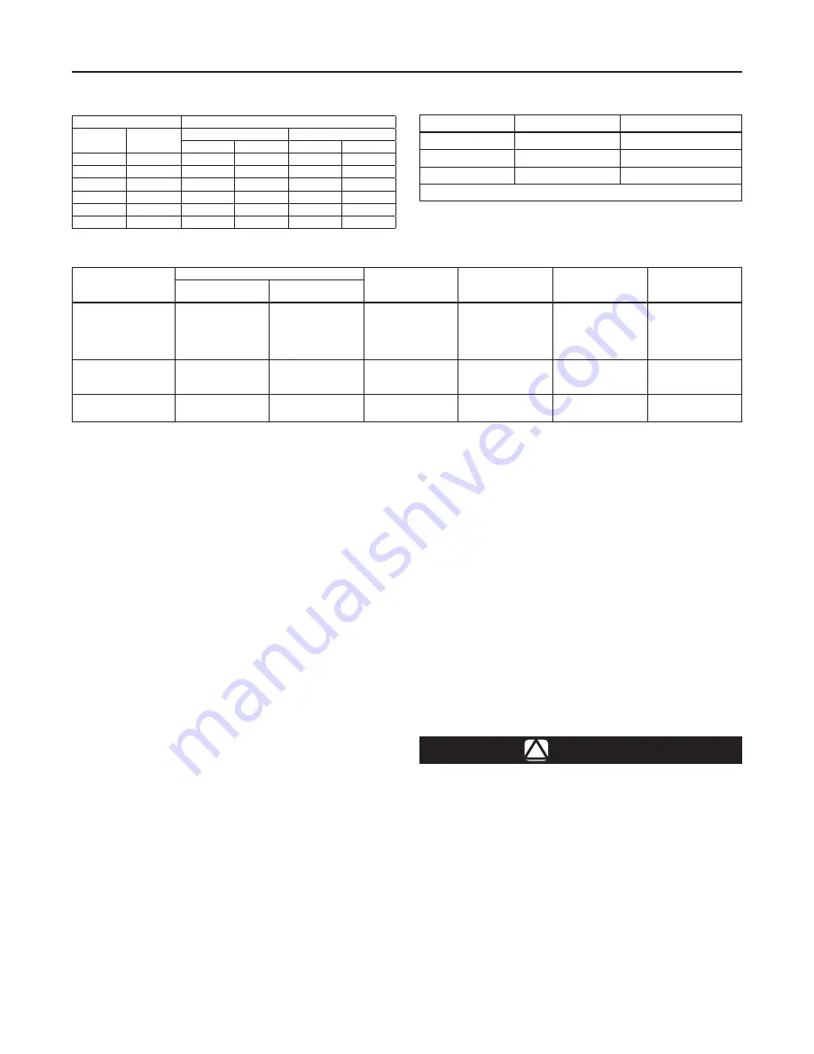
Table 1. Maximum Allowable Inlet Pressures
Table 2. Maximum Outlet Pressure Setting
ORIFICE SIzE
INLET PRESSURE SETTING
Inches
mm
Optimum
Maximum
Psig
bar
Psig
bar
1/4
6,3
125
8,6
125
8,6
3/8
9,5
100
6,9
125
8,6
1/2
13
60
4,1
100
6,9
3/4
19
25
1,7
60
4,1
1
25
13
0,90
25
1,7
1-3/16
30
5
0,34
13
0,90
TyPE NUMBER
DIAPhRAGM hEAD
MAxIMUM OUTLET*
S201, S202
Light
30-inches w.c. (75 mbar)
S201H, S202H
Heavy
5 psig (0,34 bar)
S201K
Heavy
10 psig (0,69 bar)
* Maximum emergency outlet (casing) pressure for S200 Series is 15 psig (1,0 bar).
Table 3. Outlet Pressure Ranges
TyPE NUMBER
SPRING RANGE
PART NUMBER
SPRING FREE
LENGTh,
INChES (mm)
SPRING WIRE
DIAMETER,
INChES (mm)
COLOR CODE
Inches w.c.
mbar
S201 and S202
2.0 to 4.5
3.5 to 6.5
5.0 to 9.0
8.5 to 18.0
14.0 to 30.0
5 to 11
9 to 16
12 to 22
21 to 45
35 to 75
1D892527022
1D892627022
1D892727012
1D893227032
1D893327032
6.12 (155)
7.53 (191)
7.88 (200)
7.50 (191)
7.25 (184)
0.109 (2,77)
0.112 (2,84)
0.130 (3,30)
0.156 (3,96)
0.182 (4,62)
Brown
Red
Black
Gray
Dark Green
S201H and S202H
1.0 to 2.0 psig
1.5 to 3.25 psig
2.0 to 5.0 psig
0,07 to 0,14 bar
0,10 to 0,22 bar
0,14 to 0,34 bar
1H975827032
1H975927032
1P615427142
7.09 (180)
6.91 (176)
6.50 (165)
0.225 (5,72)
0.250 (6,35)
0.295 (7,49)
Dark Blue
Orange
Yellow
S201K
2.0 to 5.5 psig
4.0 to 10.0 psig
0,14 to 0,38 bar
0,28 to 0,69 bar
0Y066427022
1H802427032
6.00 (152)
6.00 (152)
0.363 (9,22)
0.406 (10,3)
Green Stripe
Cadmium


