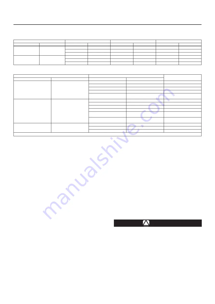
Table 1.
Maximum Operating Pressures
BODY SIZE
MAXIMUM TEMPERATURE
MAXIMUM INLET PRESSURE
MAXIMUM OUTLET PRESSURE
DN
NPS
°C
°F
bar
psig
bar
psig
15, 20, 25 and 40
1/2, 3/4, 1 and 1-1/2
65
150
14.5
210
14.5
210
135
275
12.4
180
12.4
180
204
400
11
160
11
160
50 and 80
2 and 3
65
150
10.3
150
10.3
150
135
275
8.62
125
8.62
125
204
400
7.58
110
7.58
110
Table 2.
Set Pressure Ranges and Control Spring Data
BODY SIZE
SET PRESSURE RANGE
COLOR
DN
NPS
bar
psig
15, 20
1/2, 3/4
0.2 to 0.5
(1)
2 to 8
(1)
Blue
0.4 to 1.7
5 to 25
Silver
0.7 to 3.4
10 to 50
Green
2.4 to 6.9
35 to 100
Red
5.2 to 8.6
75 to 125
Red
Yellow
25, 40 full port
40 x 25
1, 1-1/2 full port
1-1/2 x 1
0.2 to 0.5
(1)
2 to 8
(1)
Blue
0.4 to 1.7
5 to 25
Silver
1.0 to 4.8
15 to 70
Green
1.7 to 6.2
25 to 90
Red
2.4 to 6.9
35 to 100
Green
Yellow
5.2 to 8.6
75 to 125
Red
Yellow
50 and 80
2 and 3
0.7 to 1.7
10 to 25
Silver
1.0 to 3.4
15 to 50
Green
1.7 to 4.1
25 to 60
Red
1. The 0.14 to 0.55 bar / 2 to 8 psig spring is not available with the metal diaphragm.
Note
It is important that the backpressure
regulator be installed so that the vent
hole in the spring case is unobstructed
at all times.
Overpressure Protection
The recommended pressure limitations are stamped
on the nameplate.
Fisher™ backpressure regulators
are NOT ASME safety backpressure regulators.
The valve should be inspected for damage after
any overpressure condition.
Startup
The backpressure regulator is factory set at
approximately the midpoint of the spring range or the
set pressure requested, so an initial adjustment may
be required to give the desired results. With proper
installation completed, slowly open the upstream and
downstream shutoff valves.
Adjustment
To change the pressure setting, remove the closing
cap or loosen the locknut and turn the adjusting
screw or handwheel clockwise to increase pressure
or counterclockwise to decrease pressure. Monitor
the pressure with a test gauge during the adjustment.
Replace the closing cap or tighten the locknut to
maintain the desired setting.
Pressure-Loaded Construction
The spring case can be pressure loaded to adjust
set pressure. An optional tapped spring case, guide
ring seal and sealing washer on the adjusting screw
must be used for these applications. The loading
pressure is connected to the 1/4 NPT connection in
the spring case allowing registration on the spring
side of the diaphragm. Adjusting loading pressure
will proportionally change the pressure setting of the
regulator. A small amount of mechanical spring load,
in addition to the pressure load, is recommended.
Regulator set pressure achieved from the combination
of spring load and pressure load should not exceed
the set pressure ranges listed on Table 2.
Taking Out of Service (Shutdown)
!
WARNING
To avoid personal injury resulting from
sudden release of pressure, isolate
the backpressure regulator from all
pressure before attempting disassembly.
Relieve all spring compression and
isolate regulator from the pressurized
system prior to removing the clamp
(key 15, Figure 1).
Type SR8
2


