Type Y696
4
the spring and diaphragm in the Maintenance section.
To adjust the pressure setting, perform the following
steps (key numbers are referenced in figure 4):
1. Remove the closing cap (key 3).
2. Turn the adjusting screw (key 2) either clockwise to
increase control pressure or counterclockwise to
decrease control pressure. The regulator will go into
immediate operation. To ensure correct operation
always use a pressure gauge to monitor the vapor
recovery pressure when making adjustments.
3. Replace the closing cap (key 3).
Shutdown
First close the nearest upstream shutoff valve and then
close the nearest downstream shutoff valve to vent the
equipment properly. Next, open the vent valves on both
the upstream and downstream sides of the regulator. All
pressure between the shutoff valves is released through
the open vent valves.
Maintenance
Regulator parts are subject to normal wear and must be
inspected and replaced as necessary. The frequency of
inspection and replacement of parts depends upon the
severity of service conditions or the requirements of
local, state, and federal regulations. Due to the care
Fisher takes in meeting all manufacturing requirements
(heat treating, dimensional tolerances, etc.), use only
replacement parts manufactured or furnished by Fisher.
Key numbers are referenced in figure 4.
To avoid personal injury, property dam-
age, or equipment damage caused by
sudden release of pressure, isolate the
regulator from all pressure and cau-
tiously release trapped pressure from the
regulator before attempting disassembly.
Body Area
This procedure is for gaining access to the disk assem-
bly, orifice, body gasket, and split ring. All pressure
must be released from the regulator, before the following
steps can be performed.
1. To inspect and replace the disk assembly (key 25)
or orifice (key 27), remove the body cap assembly
(key 38).
2. Remove the disk screw (key 47) and cotter pin
(key 14) from the disk shut-off stem (key 40) if it is
necessary to replace the disk assembly (key 25).
3. To inspect and replace the orifice (key 27), loosen
the union nut (key 19) and separate the diaphragm case
assembly from the body (key 28).
4. Remove and inspect the body gasket (key 16).
5. Inspect and replace the orifice (key 27) if neces-
sary. Lubricate the threads of the replacement orifice
with a good grade of pipe thread sealant. Install and
tighten using 75 to 100 foot-pounds (102 to 136 N•m) of
torque.
6. If necessary, install the replacement body gasket
(key 16) into the body (key 28).
7. Slide the union nut (key 19) as far as it will go onto
the lower casing assembly (key 20). Install both halves
of the split ring (key 17) into the slots of the lower
casing assembly (key 20) and secure them by sliding
the union nut down on the split ring.
Note
In the following step, be sure to install
the spring case barrel pointed down as
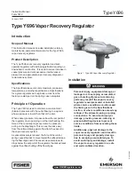
shown in figure 1.
8. Install the lower casing assembly (key 20) by
tightening the union nut (key 19) until the lower casing
assembly is secure on the body (key 28).
9. Install the disk spring (key 41) and disk assembly
(key 25) and secure it to the disk stem (key 40) with the
cotter pin (key 14). Install the disk screw (key 47).
10. Use a good quality thread sealer when replacing
the body cap assembly (key 38).
Diaphragm and Spring Case Area
This procedure is for gaining access to the control
spring, diaphragm, and lever assembly stem. All
pressure must be released from the diaphragm case
assembly before the following steps can be performed.
To Change the Control Spring:
1. Remove the closing cap (key 3), and turn the
adjusting screw (key 2) counterclockwise until all
compression is removed from the control spring (key 1).


