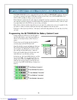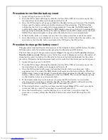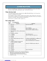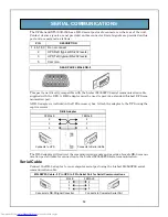
10
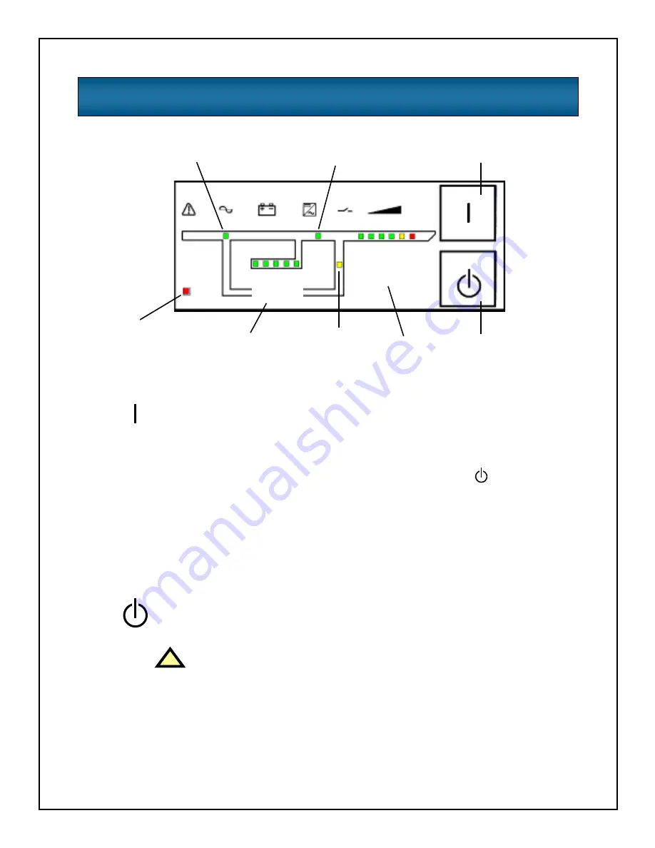
CONTROLS AND INDICATORS
ON/Manual Battery Test button
This button controls output power to connected load(s) and has two functions:
• Transfer load to inverter
• Manual battery test
Pressing the ON/Manual Battery Test button will transfer the load from bypass to
inverter in order to provide conditioned and protected power to the output power
receptacles. If the output is turned off using the Standby button
, pressing the ON
button will restart the load directly from the inverter.
To initiate a manual battery test, press the ON/Manual Battery Test button for at
least one second while operating from utility power and no alarm conditions are
present.
The manual battery test should be initiated with fully charged batteries (all Battery
Capacity LEDs on). The Battery Capacity LEDs will flash during the battery test.
Standby/Manual Bypass button
This button controls output power to connected load(s) and has dual functions:
• Standby
• Manual bypass
!
CAUTION
Pressing the Standby/Manual Bypass button during normal
operation while the inverter is on will transfer the load to bypass
power, if the bypass voltage and frequency are within a safe range.
Pressing the Standby/Manual Bypass button when the UPS is in
bypass mode will shut off power to the output receptacles and
connected loads. Turning the unit off leaves the UPS in standby
mode. To fully isolate the load from power, open the input circuit
breaker.
ON/Manual battery test
(Transfer to inverter)
On Inverter
indicator
Fault
indicator
Battery capacity
indicators
On bypass
indicator
Load level
indicators
Standby/Manual bypass
(Transfer to bypass)
1-3
5%
36-5
5%
56-7
5%
76-9
5%
96-10
5%
OV
ERL
O
AD
1-35
%
36-55
%
56-75
%
76-95
%
96-100
%
AC input
indicator


