15
OPTIONAL BATTERIES - PROGRAMMABLE RUN TIME
The GXT5000R-208 may be equipped with up to five battery GXT5VBATT cabinets. At least
one battery cabinet is required. The first battery cabinet may be a GXT5VBATTW120 if a
120V, 400VA auxiliary voltage source is needed.
The enhanced communication provides an estimated run time in minutes, taking into account
the number of battery cabinets and UPS load. The number of attached battery cabinets must
be programmed into the UPS for accurate time estimates.
Even when external monitoring software is not used, the enhanced accuracy is applied to the
low battery contact closure alarm provided by the standard relay alarm card.
The front control panel provides a convenient method of programming the number of battery
cabinets.
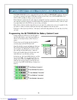
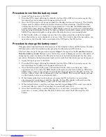
Programming the GXT5000R-208 for Battery Cabinet Count
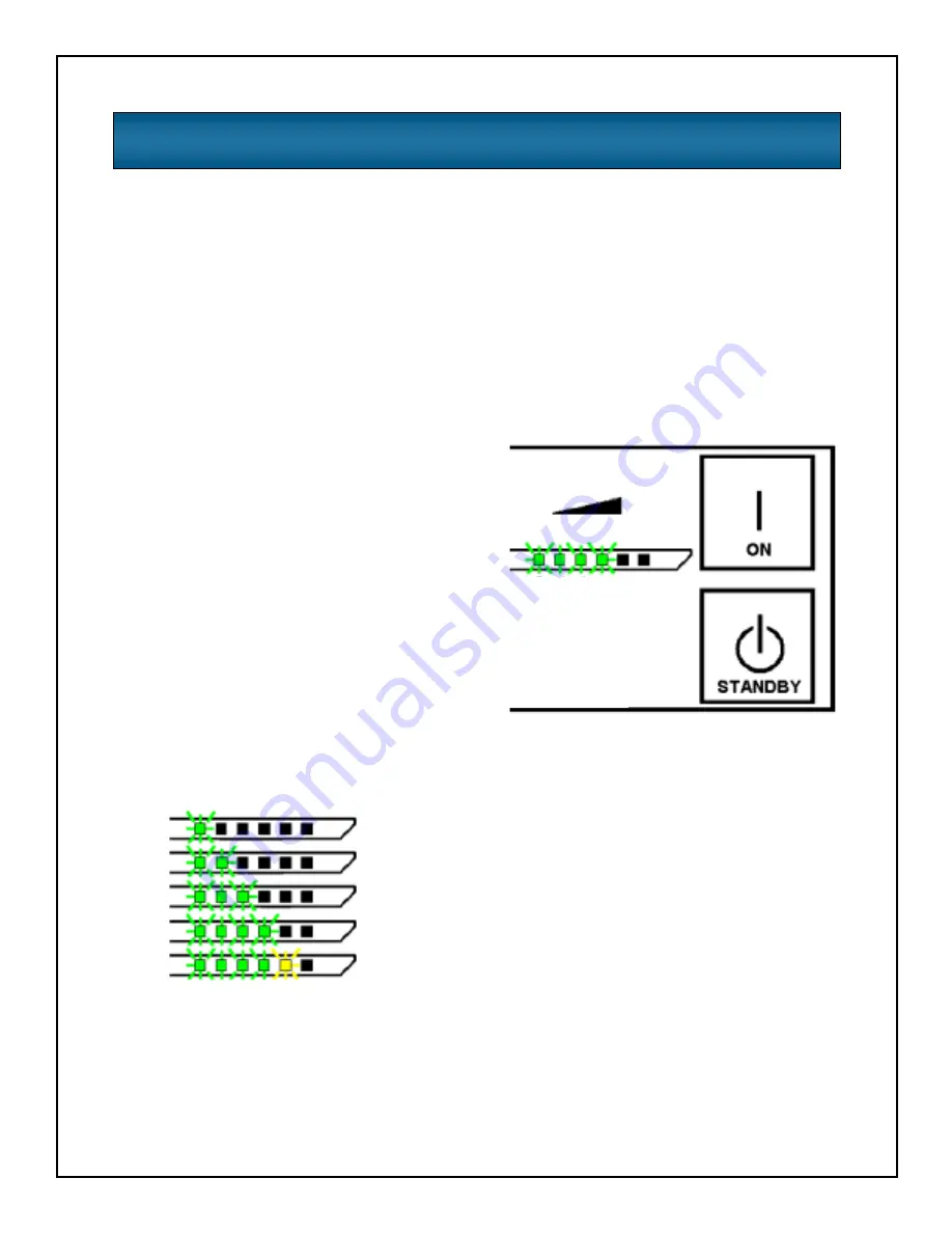
Programming the UPS uses the ON button,
the Standby button, and the Load LEDs on
the front control panel (see illustration at
right).
The battery count display mode should be
entered only with the UPS load off.
Once the battery count is displayed, the user
has the option of leaving the battery count
unchanged or modifying the count to match
the number of attached battery cabinets.
The count should always be checked on new
installations to confirm the setting.
In this mode, the Load LEDs function as Bat-
tery Count LEDs. On completion of the pro-
cedure, one to five Load LEDs illuminate to
indicate how many battery cabinets are con-
nected to the GXT5000R-208 (see illustration
below).
On
e B
a
tt
er
y
Tw
o Batteries
Fo
ur Ba
tte
rie
s
Five Batteries
T
h
ree Batter
ies
One Battery Connected
Two Batteries Connected
Three Batteries Connected
Four Batteries Connected
Five Batteries Connected


