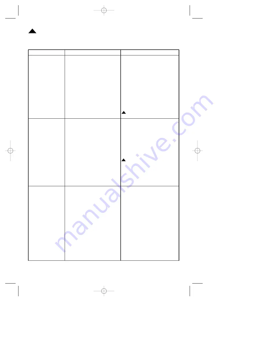
background image

14

Trouble Shooting

TROUBLE

PROBABLE CAUSE

SUGGESTED REMEDY

1. Fan will not 

1. Fuse or circuit breaker 

1. Check main and branch

start.

blown.

circuit fuses or circuit breakers.

2. Loose power line connections 

2. Check line power connections 

to the fan, or loose switch wire

to fan and switch wire  

connections in the switch 

connections in the switch 

housing.

housing.

3. Wall switch is off.

3. Turn on wall switch.

4. Defective battery in remote

4. Check that the battery is good 

control transmitter.

(red indicator light should
illuminate when any button is
pressed).

5. Code switches in remote

5. Check that both code switches

control receiver and transmitter

are set in the same positions.

are not set in the same position.

WARNING: 

Make sure 

main power is turned off.

2. Fan sounds 

1. Blades not attached to fan.

1. Attach blades to fan before

noisy.

operating.

2. Screws securing fan blade

2. Check to make sure the screws

flanges to motor are loose. 

which attach the blade flanges 
to the motor are tight. 

3. Wire connectors inside switch 

3. Check to make sure wire

housing rattling.

connectors in switch housing 
are not rattling against each
other or against the interior wall
of the switch housing.

WARNING: 

Make sure main

power is turned off.

4. Screws holding blades to 

4. Tighten screws securely.

flanges are loose.

5. Loose screws in motor housing. 5. Check to make sure all screws

in motor housing are snug
(not over-tight)

3. Fan wobbles

1. Setscrew in motor coupling is 

1. Raise coupling cover and tighten

excessively.

not tightened securely.

setscrew securely.

2. Setscrew in the hanger ball/

2. Tighten the setscrew in the

downrod assembly is loose.

hanger ball/downrod assembly.

3. Screws securing fan blade 

3. Check to be sure screws which

flanges to motor are loose.

attach the fan blade flanges 
to the motor are tight.

4. Fan blade flanges not seated 

4. Check to be sure that the

properly.

screws securing the fan 
blade flanges seat firmly.

5. Hanger bracket and/or ceiling 

5. Tighten the hanger bracket

outlet box is not securely 

screws to the outlet box, and/or 

fastened.

secure outlet box.

6. Fan blades out of balance.

6. Interchanging an adjacent (side

by-side) blade pair can 
redistribute the weight and result
in smoother operation. 
Or use supplied balancing kit to
balance blades.

WARNING: 

FOR YOUR OWN SAFETY TURN OFF POWER AT FUSE BOX

OR CIRCUIT BREAKER BEFORE TROUBLE SHOOTING YOUR FAN.

!

!

!

Emerson High Country  3/10/05  9:32 AM  Page 14

Summary of Contents for HIGH COUNTRY KF160OI00

Page 1: ... SAVE THESE INSTRUCTIONS KF160OI00 Ol ld de e Ir ro on n w wi it th h W Wa as sh he ed d Oa ak k H Ho on ne ey y M Ma ap pl le e B Bl la ad de es s HIGH COUNTRY Ceiling Fan Owner s Manual Emerson Fans Designed by Model Number Emerson High Country 3 10 05 9 32 AM Page 1 ...

Page 2: ...he outlet box Most outlet boxes commonly used for support of light fixtures are not acceptable for fan support and may need to be replaced Consult a qualified electrician if in doubt 4 The longer downrod furnished with the fan provides the minimum recom mended floor to fan blade clearance for a 9 foot ceiling The shorter downrod must be used for an 8 foot ceiling 5 The fan must be mounted with the...

Page 3: ...tor housing assembly b One upper glass c One ceiling cover d One decorative cover e Five fan blades f Five blade flanges g One hanger bracket h One hanger ball downrod assembly i One 3 1 2 downrod j One decorative cap k One finial nut l One lower glass m One decorative scroll assembly n One light fitter adapter o One light fitter assembly p One remote control transmitter q One remote control recei...

Page 4: ...nlight push buttons turn the lights on and off and controls the light intensities The red indicator light will illuminate while any button is pressed indicating that the battery is good Preset Memory Feature Your remote control receiver is equipped with a preset memory feature The receiv er will remember the light intensity and fan speed when the light and fan are turned off from the wall switch W...

Page 5: ... fuse or circuit breaker box before wiring All wiring must be in accordance with National and Local codes and the ceiling fan must be properly grounded as a precaution against possible electrical shock WARNING How to Assemble Your Ceiling Fan 1 Place the motor housing assembly on a flat surface with the top of the motor facing upwards Place the upper glass over the motor housing assembly aligning ...

Page 6: ...is pin until the curved portion of the hairpin clip snaps around the clevis pin The hairpin clip must be properly installed to prevent the clevis pin from working loose Pull up on the downrod to make sure the clevis pin is properly installed 4 Remove and discard the three shipping retainers securing the motor hub in the motor housing NOTE Take care not to scratch the fan housing when installing th...

Page 7: ...roll 12 Place the ceiling cover over the down rod Then reinstall the hanger ball Figure 8 on the downrod as follows Route the four 80 motor leads through the hanger ball and slide the hanger ball over the downrod Position the pin through the two holes in the downrod and align the hanger ball so the pin is captured in the groove in the top of the hanger ball Pull the hanger ball up DOWNROD MOTOR CO...

Page 8: ...gure 10 Hanger bracket must seat firmly against outlet box If the outlet box is recessed remove wall board until bracket contacts box If bracket and or outlet box are not securely attached the fan could wobble or fall WARNING Failure to seat tab in groove could cause damage to electrical wires and possible shock or fire hazard WARNING To avoid possible fire or shock do not pinch wires between the ...

Page 9: ...3 and connect the receiver wires to the supply wires and the fan motor wires as follows a Securely connect the green grounding wires from the hanger ball and the hanger bracket to the supply grounding conductor this may be a bare wire or a wire with green insulation b Securely connect the supply white neutral wire to the receiver white AC IN N wire c Securely connect the supply black wire hot wire...

Page 10: ...TIONAL SW115 WALL CONTROL BLACK BLACK WHITE BLACK BLACK WHITE HANGER BALL GREEN WIRE GROUND FROM HANGER BALL AND HANGER BRACKET TWO CONDUCTOR CABLE WITH GROUND BLACK HOT WHITE GROUND TO 120 VOLT SUPPLY WHITE BLUE BLUE ORANGE ORANGE WHITE Figure 13 3 Push the wires and connectors up into the outlet box while inserting the receiv er fully into the hanger bracket Position the antenna wire on top of t...

Page 11: ...om the motor Figure 16 Connect the black wire from the light fitter to the black wire from the motor Make sure connectors are fully engaged 9 Position the adapter light fitter assem bly over the adapter plate and secure using three 8 32 x 12mm pan head screws Figure 17 BLACK WIRE WHITE WIRE LIGHT FITTER ADAPTER PLATE ADAPTER Figure 16 11 8 32 x 12mm PAN HEAD SCREW 3 ADAPTER LIGHT FITTER ASSEMBLY F...

Page 12: ...n the downlight on press and release the DN button The light will turn on at the light intensity previously selected 6 To turn the uplight on press and release the UP button The light will turn on at the light intensity previously selected 7 To vary the intensity of the light hold the DN or UP button down until the desired light intensity is reached then release the button Red light should turn on...

Page 13: ...terference in a residential installation This equipment generates uses and can radiate radio frequency energy and if not installed and used in accor dance with the instructions may cause harmful interference to radio communications However there is no guarantee that interference will not occur in a particular installation If this equipment does cause harmful interference to radio or television rec...

Page 14: ...ttling against each other or against the interior wall of the switch housing WARNING Make sure main power is turned off 4 Screws holding blades to 4 Tighten screws securely flanges are loose 5 Loose screws in motor housing 5 Check to make sure all screws in motor housing are snug not over tight 3 Fan wobbles 1 Setscrew in motor coupling is 1 Raise coupling cover and tighten excessively not tighten...

Page 15: ...n 762635 6 23 Flange Set full set for one fan 762723 OI 24 Harness Assembly Wiring 762704 25 Adapter Fitter 762703 OI 26 Fitter Assembly Light 762705 27 Glass Lower 762702 28 Glass Upper 762701 29 Cap Decorative 762706 OI 30 Nut Finial 762707 OI 31 Downrod 3 1 2 761631 42 32 Receiver Remote Control 762670 2 33 Transmitter Remote Control 762402 Owner s Manual BP7283 1 Before discarding packaging ma...

Page 16: ...er You will be responsible for all insurance freight or other transportation charges to our fac tory or authorized service center Your Emerson Air Comfort Ceiling Fan should be properly packed to avoid damage in transit since we will not be responsible for any such damage What Is Not Covered The glass globes and light bulbs of your ceiling fan are not covered by this warranty This warranty also do...

Reviews: