background image

5

KEYSTONE

 FIGURE 79 PNEUMATIC ACTUATOR

OPERATING AND MAINTENANCE INSTRUCTIONS

NOTES

Refer to notes on page 4 as indicated.

12.  Fit ‘O’-ring seals (item 14) to endcaps (item 

3) using a light smear of grease.

13. Fit endcap spring assemblies to body and 

alternately tighten the endcap screws 
(item 15) until secure (see recommended 
torque table).

14. Fit position indicator to top of actuator.
15. Operate the actuator to OPEN & CLOSE 

positions using compressed air and note the 
actual positions. If the required travel is not 
achieved refer to page 10.

Fail Open Units

7.  Insert pistons (item 2) complete with 

backing pads (1) (item 18) and backing rings 
(4) as follows:-

  - with piston legs on 

right side

 of bore 

(when viewed from the o-ring end of the 
piston), until racks engages with pinion and 
then push fully inward, the actuator is now 
in the fully open position.


Note:

 If no travel stops are fitted proceed to 

instruction 12.

8.   Turn the pinion shaft clockwise 

approximately 5° until it is orientated in line 
with the major axis of the actuator body. The 
shaft is now in the open position.

9.   Insert Open travel stop bolt (item 19/20) 

together with sealing nut or lock nut (2)(3), 
flat washer (2)(3) and sealing washer (2)
(3) until the bolt hits the travel stop cam. 
Tighten the lock nut.

10.  Turn the pinion shaft clockwise through 90° 

to bring it in line with the center line of the 
actuator bore, the actuator is now in the 
close position.

11. Insert CLOSE travel stop bolt (item 19/20) 

together with sealing nut or lock nut (2)(3), 
flat washer (2)(3) and sealing washer (2)
(3) until the bolt hits the travel stop cam. 
Tighten the lock nut.

Fail Close Units

7.  Insert pistons (item 2) complete with 

backing pads(1)(item 18) and backing 
rings(4) as follows:-

   - with piston legs on 

left side

 of bore (when 

viewed from the o-ring end of the piston), 
until racks engages with pinion and then 
push fully inward, the actuator is now in the 
fully closed position.


Note:

 If no travel stops are fitted proceed to 

instruction 12.

8.  Turn the pinion shaft anti-clockwise 

approximately 5° until it is orientated in line 
with the major axis of the actuator body. The 
shaft is now in the closed position.

9.  Insert CLOSE travel stop bolt (item 19/20) 

together with sealing nut or lock nut (2)(3), 
flat washer (2)(3) and sealing washer (2)
(3) until the bolt hits the travel stop cam. 
Tighten the lock nut.

10. Turn the pinion shaft anti-clockwise through 

90° to bring it back in line with the center 
line of the actuator bore, the actuator is now 
in the open position.

11. Insert Open travel stop bolt (item 19/20) 

together with sealing nut or lock nut (2)(3), 
flat washer (2)(3) and sealing washer (2)
(3) until the bolt hits the travel stop cam. 
Tighten the lock nut.

ASSEMBLY - SINGLE ACTING UNITS

Note:

 Please refer to the exploded views 

further on.
Liberally grease actuator bore, pistons and 
pinion assembly with Molyrace LT
lubricant.

Note:

 The endcap spring assembly is a 

complete module with the appropriate spring 
preset to suit the selected duty parameters. 
Spring retaining bolt threads are bonded to end 
caps with threadlock sealant to ensure double 
security.

Caution!

 No attempt should be made to remove 

or adjust spring retaining bolts.
1.  Coat all ‘O’-ring seals with Molyrace LT 

lubricant.

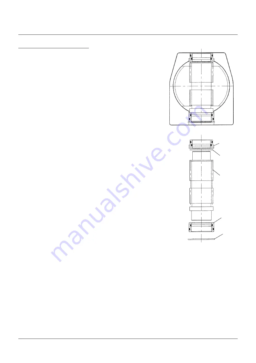
2.  Output shaft assembly:-
  a)  Fit the top bearing assembly (item 9) into 

the top bore of the actuator body (item 1) 
with the outer o-ring uppermost.

  b)  Fit the bottom bearing assembly (item 6) 

on to the bottom of the pinion shaft (item 
5) with internal o-ring uppermost.

3.   Insert pinion shaft assembly from underside 

of the actuator as shown in the diagram 
opposite.

4.  Fit internal circlip (item 12) to bottom recess 

of body to locate the shaft assembly.

5.  Fit ‘O’-ring seals (item 13) on pistons (item 2).
6.  Orientate output shaft at 45° ± 2°.

FIGURE 4

Sectioned assembly of actuator 

body and output shaft

Top bearing 

assembly

Gear shim as 

required

See note 4

Output shaft

Bottom bearing 

assembly

Internal circlip

Summary of Contents for KEYSTONE FIGURE 79E

Page 1: ...e fitting sealants are used they should be applied to the male threads only When applied to female threads excess compound can be transmitted into the actuator control lines 6 Where a system is dependent on Air Filter Equipment the air filters should be situated in positions that allow easy access to maintain and or drain 7 Where pneumatic valve positioners or pneumatic controllers are fitted to v...

Page 2: ...ed it may be necessary to fit the valve into the pipeline prior to mounting the actuator to the valve Rubber lined butterfly valves are an example of this 7 For valves which need to be installed in the pipeline prior to fitting the actuator ensure that the valve is operated into its failsafe position before mounting the actuator onto the valve NON STANDARD INSTALLATION DOUBLE SINGLE ACTING UNITS I...

Page 3: ...ng the use of eye protection Always ensure that spring return actuators are in fail safe position before attempting any maintenance Pay particular attention to this requirement when manual operators are fitted For safety reasons DONOT Air Assist Single Acting Pneumatic actuators 1 Pull off the indicator cap item 17 from the top of the actuator If this cap is too tight light pressure may be applied...

Page 4: ...ether with sealing nut or lock nut 2 3 flat washer 2 3 and sealing washer 2 3 NOTES 1 Backing pads are not required on 002 003 models which have nylon pistons 2 Lock nuts flat washers and sealing washers are only fitted to models 065 180 3 On models 003 036 the lock nut sealing nut are one item 4 Gear shim is required on models 006 and 012 only 5 Backing rings and pads are only fitted to models 06...

Page 5: ...inward the actuator is now in the fully closed position Note If no travel stops are fitted proceed to instruction 12 8 Turn the pinion shaft anti clockwise approximately 5 until it is orientated in line with the major axis of the actuator body The shaft is now in the closed position 9 Insert CLOSE travel stop bolt item 19 20 together with sealing nut or lock nut 2 3 flat washer 2 3 and sealing was...

Page 6: ...ons in Open position Pistons out Top view of Actuator Closed position Pistons out Open position Pistons in FIGURE 5 NON STANDARD FAIL OPEN SINGLE ACTING ACTUATOR ASSEMBLY 79U E MODELS 002S 036S End cap O ring Backing pad Body O ring Hex head screws Lock washer Piston Direction of movement End cap spring hsg O ring Backing pad Body O ring Hex head screws Lock washer Piston Direction of movement End...

Page 7: ...istons in Open position Pistons out Top view of Actuator Closed position Pistons out Open position Pistons in FIGURE 9 Closed position Pistons out Open position Pistons in FIGURE 8 FIGURE 10 End cap O ring Backing ring Travel bolts Close Open Body O ring Hex head screws Lock washer Piston Direction of movement Travel bolts Models 090S 180S Model 065S only Close Open End cap spring hsg O ring Backi...

Page 8: ...O Ring 1 Nitrile 9 Top Bearing 1 Polymer 10 Top Bearing Internal O Ring 1 Nitrile 11 Top Bearing External O Ring 1 Nitrile 12 Internal Circlip 1 Spring steel 13 Piston O ring 2 Nitrile 14 End Cap O ring 2 Nitrile 15 Hex Screw M5 x 16 002 003 M5 x 20 006 M8 x 25 012 M10 x 30 024 036 8 Stainless steel 16 Lock Washer M5 002 006 M8 012 M10 024 036 8 Steel 17 Position Indicator 1 ABS 18 Backing pad 2 P...

Page 9: ... ring 2 Nitrile 14 End Cap O ring 2 Nitrile 15 Hex Screw M5 x 16 002 003 M5 x 20 006 M8 x 25 012 M10 x 30 024 036 8 Stainless steel 16 Lock Washer M5 002 006 M8 012 M10 240 036 8 Steel 17 Position Indicator 1 ABS 18 Backing pad 2 Polymer 006 036 19 Travel Stop Bolt M6 x 25 003 M8 x 45 006 M10 x 50 012 M12 x 65 024 036 2 Stainless Steel 20 Travel Stop Nut M6 003 M8 006 M10 012 M12 024 036 2 Steel P...

Page 10: ...ing External O Ring 1 Nitrile 9 Top Bearing 1 Polymer 10 Top Bearing Internal O Ring 1 Nitrile 11 Top Bearing External O Ring 1 Nitrile 12 Internal Circlip 1 Spring steel 13 Piston O ring 2 Nitrile 14 End Cap O ring 2 Nitrile 15 Hex Screw M12 x 40 065 090 M16 x 55 180 8 Stainless steel 16 Lock Washer M12 065 090 M16 180 8 Steel 17 Position Indicator 1 ABS 18 Backing pad 4 Polymer 19 Travel Stop Bo...

Page 11: ...ton O ring 2 Nitrile 14 End Cap O ring 2 Nitrile 15 Hex Screw M12 x 40 065 090 M16 x 55 180 8 Stainless steel 16 Lock Washer M12 065 090 M16 180 8 Steel 17 Position Indicator 1 ABS 18 Backing pad 4 Polymer 19 Travel Stop Bolt M16 x 65 065 M16 x 90 090 M20 x 130 180 2 Stainless steel 20 Travel Stop Nut M16 065 090 M20 180 2 Stainless steel 21 Washer Flat M16 M20 2 Stainless steel 22 Washer Thread S...

Page 12: ...ses travel 4 Re tighten lock nut 5 Remove air so that actuator closes If correct closed position is not achieved repeat from instruction 2 6 Slacken locknut on the open stop and adjust the travel by an amount estimated to give correct position clockwise adjustment decreases travel 7 Re tighten locknut 8 Apply air and check open position If correct open position is not achieved Repeat from instruct...

Page 13: ...tic actuators RECOMMENDED TIGHTENING TORQUES FOR END CAPS Torque Models Bolt Diameter Nm lbs ft STANDARD SPRING COLOR CODES Spring Rating Models 003S to 180S End 1 End 2 40 psi 2 8 bar Light Blue Light Blue 50 psi 3 5 bar Light Blue White 60 psi 4 2 bar White White 70 psi 4 8 bar Light Blue Dark Blue White 80 psi 5 5 bar Light Blue Dark Blue Light Blue Dark Blue 90 psi 6 2 bar Light Blue White Lig...

Reviews: